Figure 28-43 – Motorola ColdFire MCF5281 User Manual
Page 592
Queued Analog-to-Digital Converter (QADC)
28-54
Freescale Semiconductor
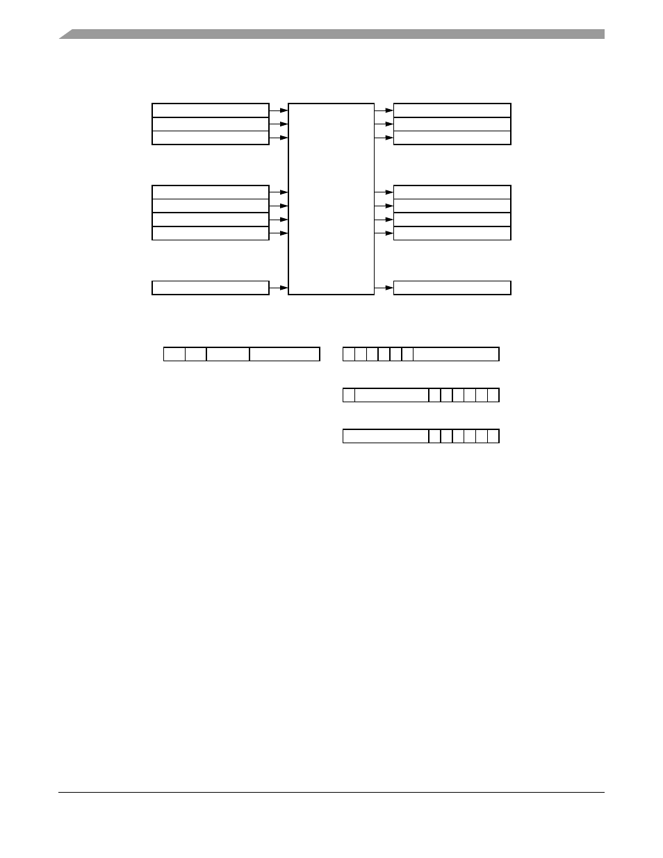
Figure 28-43. QADC Conversion Queue Operation
To prepare the QADC for a scan sequence, write to the CCW table to specify the desired channel
conversions. The criteria for queue execution is established by selecting the queue operating mode. The
queue operating mode determines what type of trigger event starts queue execution. A trigger event refers
to any of the ways that cause the QADC to begin executing the CCWs in a queue or subqueue. An external
trigger is only one of the possible trigger events.
A scan sequence may be initiated by:
•
A software command
•
Expiration of the periodic/interval timer
•
An external trigger signal
•
An external gated signal (queue 1 only)
The queue can be scanned in single pass or continuous fashion. When a single-scan mode is selected, the
scan must be engaged by setting the single-scan enable bit. When a continuous-scan mode is selected, the
queue remains active in the selected queue operating mode after the QADC completes each queue scan
sequence.
During queue execution, the QADC reads each CCW from the active queue and executes conversions in
three stages:
•
Initial sample
•
Final sample
Beginning of Queue 1
00
Channel Select,
Sample, Hold,
A/D Conversion
Conversion Command
Result Word Table
Word (CCW) Table
00
End of Queue 1
Beginning of Queue 2
End of Queue 2
63
63
•
•
•
•
•
•
•
•
•
•
•
•
BYP
P
IST
CHAN
8
9
[7:6]
[5:0]
P — Pause after Conversion
until Next Trigger
BYP — Bypass Buffer Amplifier
IST — Input Sample Time
CHAN — Channel Number and
End-of-Queue Code
10-bit Conversion Command
Word Format
0
RESULT
[9:0]
10-bit Result, Readable in
Three 16-BIT Formats
0 0 0 0 0
15 14 13 12 11 10
0
RESULT
0 0 0 0 0
Right-Justified, Unsigned Result
Left-Justified, Unsigned Result
Left-Justified, Signed Result
0
RESULT
0 0 0 0 0
S
[5:0]
[5:0]
[15:6]
[15:6]
MCF5282 and MCF5216 ColdFire Microcontroller User’s Manual, Rev. 3