Motorola ColdFire MCF5281 User Manual
Page 597
Queued Analog-to-Digital Converter (QADC)
Freescale Semiconductor
28-59
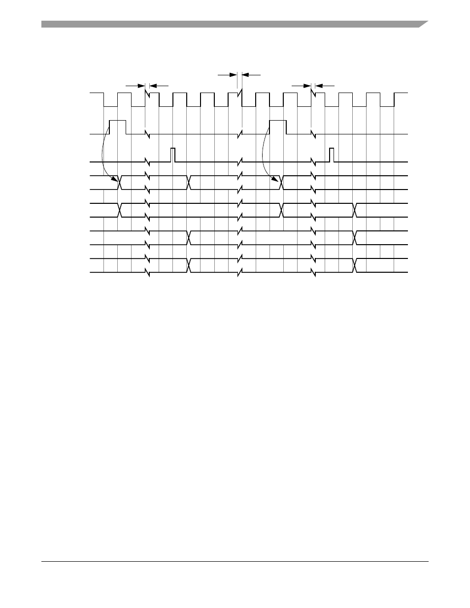
Figure 28-46. External Positive Edge Trigger Mode Timing with Pause
A time separator is provided between the triggers and the end of conversion (EOC). The relationship to
QCLK displayed is not guaranteed.
CWPQ1 and CWPQ2 typically lag CWP and only match CWP when the associated queue is inactive.
Another way to view CWPQ1 and CWPQ2 is that these registers update when EOC triggers the write to
the result register.
For the CCW with the pause bit set (CCW0), CWP does not increment until triggered. For the CCW with
the pause bit clear (CCW1), the CWP increments with the EOC.
The conversion results Q1 RESx show the result associated with CCWx, such that R0 represents the result
associated with CCW0.
shows the timing for conversions in externally gated single-scan with same assumptions in
example 1 except:
•
No pause bits set in any CCW
•
Externally gated single scan mode for Q1
•
Single scan enable bit (SSE1) is set.
When the gate closes and opens again, the conversions start with the first CCW in Q1.
When the gate closes, the active conversion completes before the queue goes idle.
When Q1 completes, both the CF1 bit sets and the SSE bit clears.
In this mode, the PF1 bit sets to reflect that a gate closing occurred before the queue completed.
shows the timing for conversions in externally gated continuous scan mode with the same
assumptions as in
R1
LAST
R0
CCW0
CCW1
CCW2
CCW1
CONVERSION TIME
TIME BETWEEN
QCLK
TRIG1
EOC
QS
CWP
CWPQ1
Q1 RES
0
LAST
8
4
8
CCW0
TRIGGERS
= 14 QCLKS
CONVERSION TIME
= 14 QCLKS
MCF5282 and MCF5216 ColdFire Microcontroller User’s Manual, Rev. 3