1 introduction, 1 overview, 2 block diagram – Motorola ColdFire MCF5281 User Manual
Page 361: 3 low-power mode operation, Chapter 19, Programmable interrupt timers (pit0–pit3), 1 introduction -1
Freescale Semiconductor
19-1
Chapter 19
Programmable Interrupt Timers (PIT0–PIT3)
19.1
Introduction
This chapter describes the operation of the four programmable interrupt timer modules: PIT0–PIT3.
19.1.1
Overview
Each PIT is a 16-bit timer that provides precise interrupts at regular intervals with minimal processor
intervention. The timer can count down from the value written in the modulus register or it can be a
free-running down-counter.
19.1.2
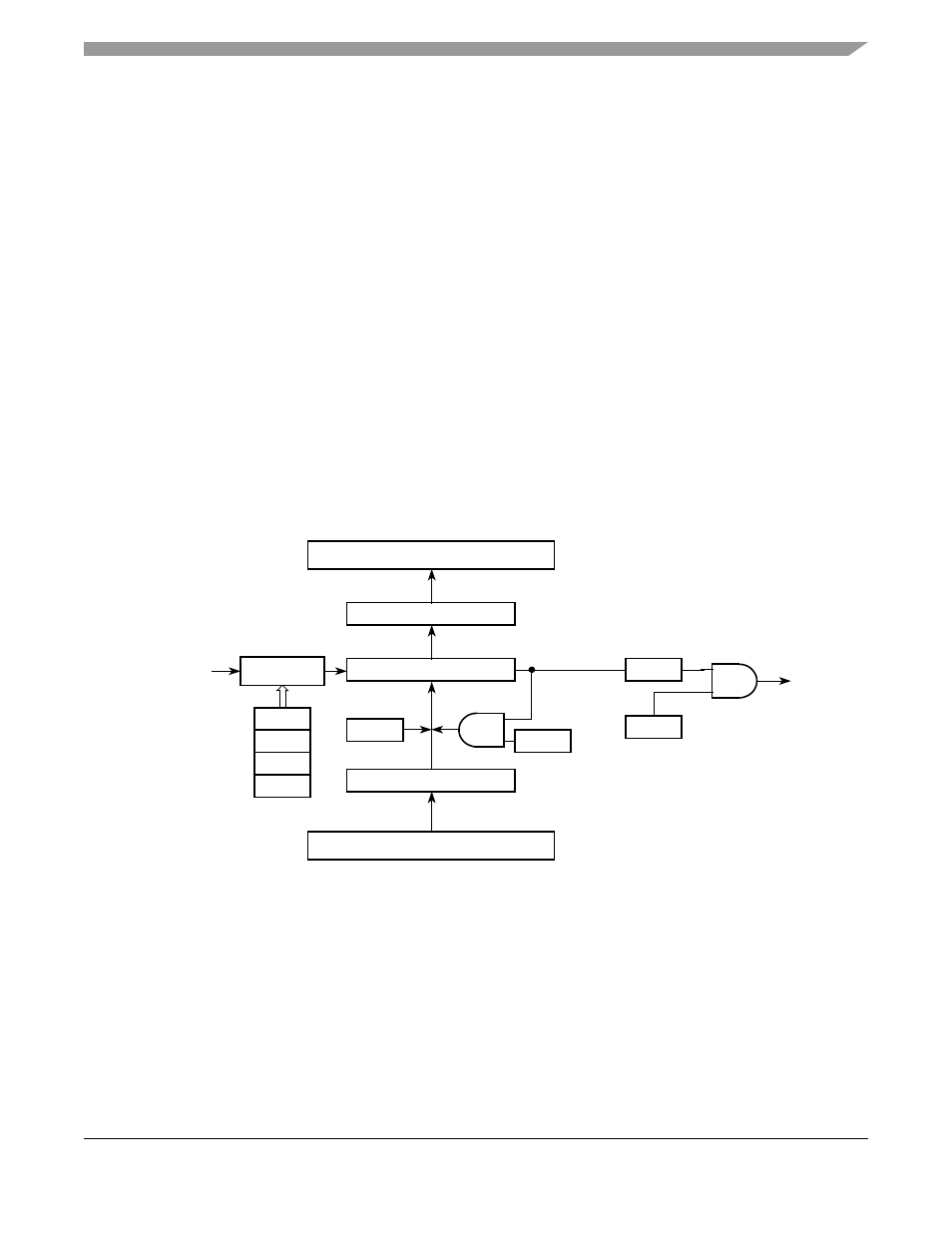
Block Diagram
Figure 19-1. PIT Block Diagram
19.1.3
Low-Power Mode Operation
This subsection describes the operation of the PIT modules in low-power modes and debug mode of
operation. Low-power modes are described in the power management module,
shows the PIT module operation in low-power modes and how it can exit from
each mode.
Internal Bus
Clock (f
sys
)
16-bit PMRn
16-bit PIT Counter
COUNT = 0
Internal Bus
16-bit PCNTRn
Internal Bus
EN
OVW
DOZE
DBG
Prescaler
PRE[3:0]
RLD
PIF
PIE
Load
Counter
To Interrupt
Controller
MCF5282 and MCF5216 ColdFire Microcontroller User’s Manual, Rev. 3