2 conversion cycle times, 2 conversion cycle times -32, E result of the conversion – Motorola ColdFire MCF5281 User Manual
Page 570: Figure 28-19
Queued Analog-to-Digital Converter (QADC)
28-32
Freescale Semiconductor
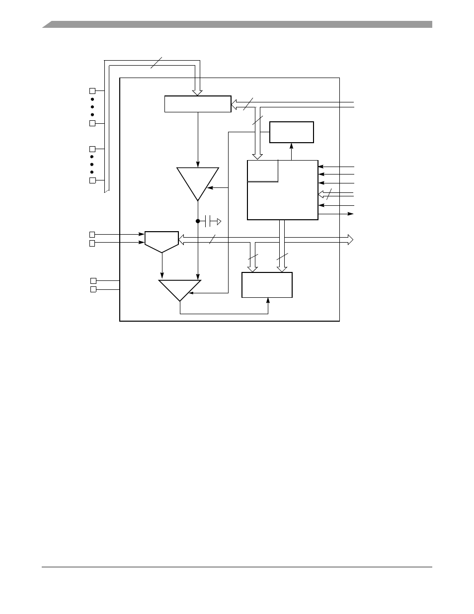
Figure 28-19. QADC Analog Subsystem Block Diagram
28.7.3.2
Conversion Cycle Times
Total conversion time is made up of initial sample time, final sample time, and resolution time. Initial
sample time refers to the time during which the selected input channel is coupled through the sample buffer
amplifier to the sample capacitor. The sample buffer is used to quickly reproduce its input signal on the
sample capacitor and minimize charge sharing errors. During the final sampling period the amplifier is
bypassed, and the multiplexer input charges the sample capacitor array directly for improved accuracy.
During the resolution period, the voltage in the sample capacitor is converted to a digital value and stored
in the SAR as shown in
.
Initial sample time is fixed at two QCLK cycles. Final sample time can be 2, 4, 8, or 16 QCLK cycles,
depending on the value of the IST field in the CCW. Resolution time is 10 QCLK cycles.
A conversion requires a minimum of 14 QCLK cycles (7
μs with a 2.0-MHz QCLK). If the maximum final
sample time period of 16 QCLKs is selected, the total conversion time is 28 QCLKs or 14
μs (with a
2.0-MHz QCLK).
PQA4
PQA0
PQB3
PQB0
V
DDA
V
SSA
V
RH
V
RL
QCLK
Start Conv
End OF Conv
RST
STOP
SAR[9:0]
10-bit A/D Converter
Input
Analog
Power
2
IST
Sample
Compar-
Successive
ator
Bias Circuit
Approximation
Register
Buffer
10
10
CHAN[5:0]
CSAMP
10
Chan. Decode & MUX
16:1
Signals F
rom/to Queue
Contro
l Logic
16
State Machine & Logic
Power-
Down
Internal
Channel
Decode
SAR Timing
4
6
MCF5282 and MCF5216 ColdFire Microcontroller User’s Manual, Rev. 3