Accton Technology ES4626 User Manual
Page 473
473
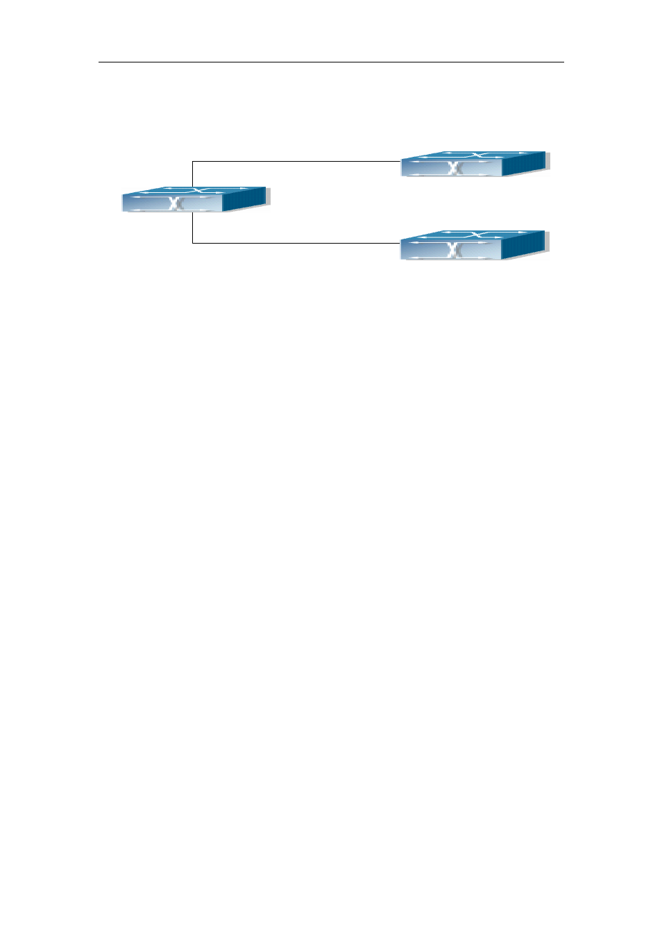
Fig 13-8 OSPF VPN Example
The above figure shows that a network consists of three Layer 3 switches in which the
switchA as PE, SwitchB and SwitchC as CE1 and CE2. The PE is connected to CE1 and
CE2 through vlan1 and vlan2. The routing messages are exchanged between PE and CE
through OSPF protocol.
a) SwitchA, the Layer 3 switch as PE
Configure VPN route/transmitting examples vpnb and vpnc
SwitchA#config
SwitchA(config)#ip vrf vpnb
SwitchA(config-vrf)#
SwitchA(config-vrf)#exit
SwitchA#(config)
SwitchA(config)#ip vrf vpnc
SwitchA(config-vrf)#
SwitchA(config-vrf)#exit
Associate the vlan 1 and vlan 2 respectively with vpnb and vpnc while configuring IP
address
SwitchA(config)#in vlan1
SwitchA(config-if-Vlan1)#ip vrf forwarding vpnb
SwitchA(config-if-Vlan1)#ip address 10.1.1.1 255.255.255.0
SwitchA(config-if-Vlan1)#exit
SwitchA(config)#in vlan2
SwitchA(config-if-Vlan2)#ip vrf forwarding vpnc
SwitchA(config-if-Vlan2)#ip address 20.1.1.1 255.255.255.0
SwitchA(config-if-Vlan2)#exit
Configure OSPF examples associated with vpnb and vpnc respectively
SwitchA(config)#
SwitchA(config)#router ospf 100 vpnb
vlan2:20.1.1.1/24
SwitchA
SwitchC
Interface
Vlan2:20.1.1.2/24
vlan1:10.1.1.2/24
Interface
vlan1:10.1.1.1/24
Interface
SwitchB