Figure 4-3, Boot flash switching, Functional description – Artesyn ATCA-8310 Installation and Use (May 2014) User Manual
Page 74: 2 boot bank selection and reprogramming
Functional Description
ATCA-8310 Installation and Use (6806800M72E)
74
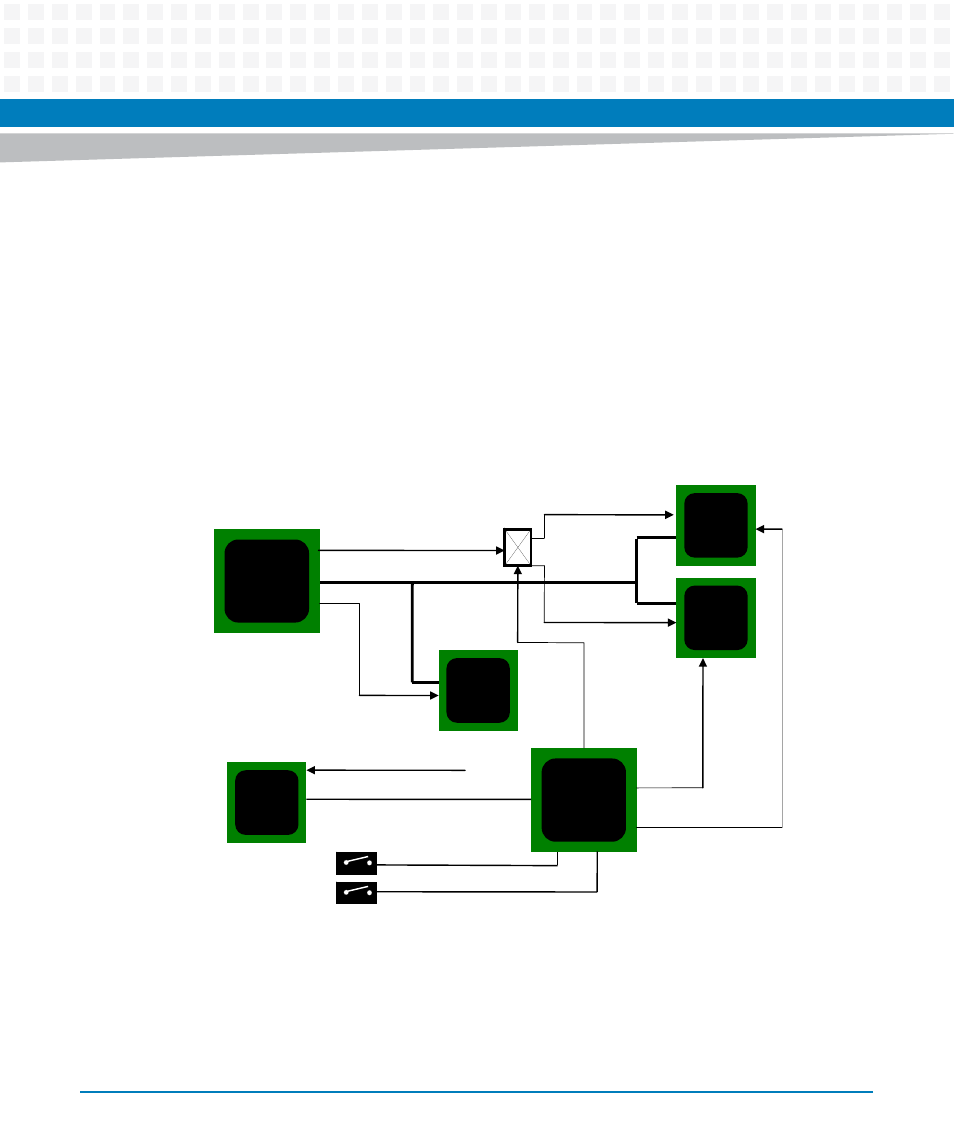
4.2.1.2.2 Boot Bank Selection and Reprogramming
By default, the payload processor boots from Boot Flash device #1. An IPMI OEM command can
be used to send a message to the IPMC to change the boot device. The IPMC provides an IPMI
sensor to control the signal BOOT_SELECT. Write protection is implemented through the
FPGA.
The update mechanism is described in the software specification. The principal is to store the
information which device was used to boot from and keep that device protected. The
redundant device can then be upgraded as needed.
In case of an IPMC firmware upgrade, the BOOT_SELECT signal stays unchanged. Besides
others, this signal is latched by a latch buffer to ensure that its state doesn't change when the
IPMC resets hard.
Figure 4-3
Boot Flash Switching
Glue
FPGA
SPI
Flash
#1
SPI
ͲInterface
ACS
8520
P4080
CS0/1#
CS1#
SPI
Flash
#2
Boot1_CS0/1#
Boot2_CS1/0#
IPMC_BOOTSEL#
Manual_BOOTSEL#
IPMC
BOOT_SELECT#
WP
WP
P4080
ͲRESET