Table 8-114, Telecom clock monitor status register, Table 8-115 – Artesyn ATCA-8310 Installation and Use (May 2014) User Manual
Page 321: Telecom clock monitor out of range register, Table 8-113, Telecom clock monitor control register, Cpld and fpga
CPLD and FPGA
ATCA-8310 Installation and Use (6806800M72E)
321
Table "Telecom Clock Monitor Status Register" on page 321
is set, the
corresponding status bit CLK_MONITOR_FINISHED of
Table "Telecom Clocking Interrupt Status
is also set.
Table "Telecom Clock Monitor Out of Range Register" on page 321
set, the corresponding status bit CLK_MONITOR_OUT_OF_RANGE of
Interrupt Status Register" on page 338
is also set.
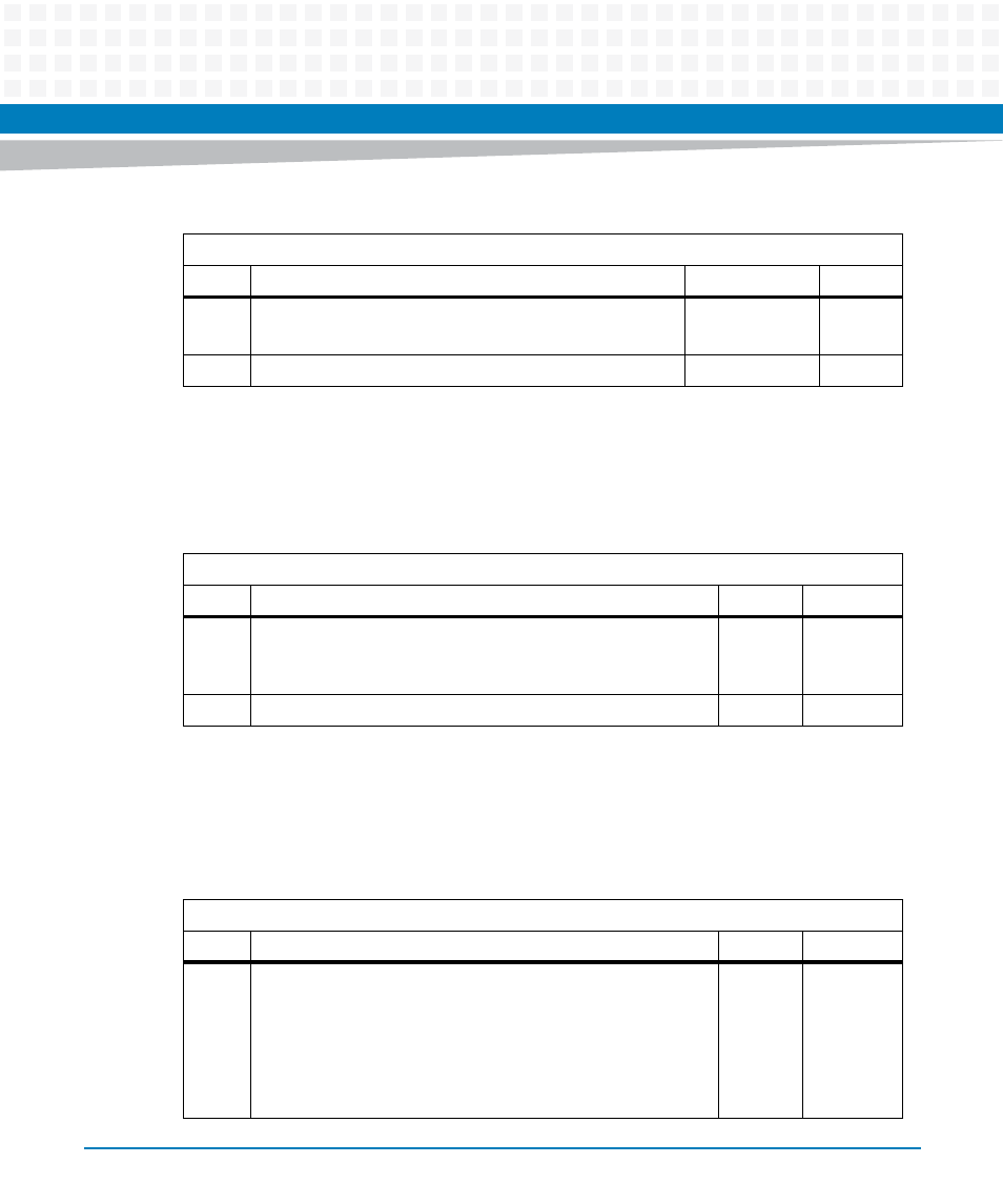
Table 8-113 Telecom Clock Monitor Control Register
Address: 0x62 - 0x63
Bit
Description
Default
Access
7:0
Enable supervised Telecom Clocks 0 to 7.
Set corresponding bit enable monitoring.
PWR_GOOD: 0
SPP: r/w
15:8
Reserved
0
r
Table 8-114 Telecom Clock Monitor Status Register
Address: 0x64 - 0x65
Bit
Description
Default
Access
7:0
Result available for supervised Telecom Clocks 0 to 7.
Corresponding bit is set when measurement has finished.
Clearing bit triggers new measurement.
0
SPP: r/w1c
15:8
Reserved
0
r
Table 8-115 Telecom Clock Monitor Out of Range Register
Address: 0x66 - 0x67
Bit
Description
Default
Access
7:0
Frequency of supervised Telecom Clocks 0 to 7i.s out of range.
Corresponding bit is set when the number of positive clock
edges within the selected time base is:
< Lower limit or
> Upper limit
Clearing bit triggers new sequence of measurements.
0
SPP: r/w1c