Cpld and fpga, 1 power-up cpld, 1 power-up cpld architectural overview – Artesyn ATCA-8310 Installation and Use (May 2014) User Manual
Page 245: Figure 8-1, Power-up cpld overview, Chapter 8, Figure 8-1 power-up cpld overview
Chapter 8
ATCA-8310 Installation and Use (6806800M72E)
245
CPLD and FPGA
8.1
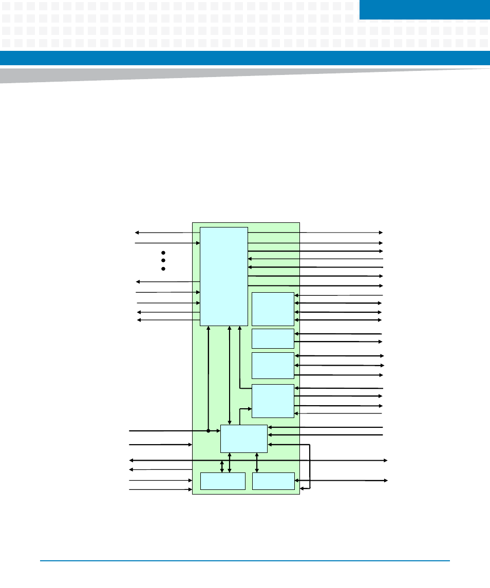
Power-up CPLD
The Power-Up CPLD is supplied by the Management Power.
8.1.1
Power-up CPLD Architectural Overview
Figure 8-1
Power-up CPLD Overview
FPGA SPI Slave Interface
Power Up State
machine
PWRGD_VXXX
PWREN_VXXX
PWRGD_VXXX
PWREN_VXXX
PWROK_KAWELA
GPP_THERMTRIP_
CPLD_PWR_GOOD
PWR_GOOD to Glue FPGA
IPMC
Latch & Bu
īer
Logic
CPLD
Registers
CONF_CRC_ERR
APB_ALARM
PCH PM Status Signals
TSALL
PWR_TRACKDWN_VP
DISCHARGE_VP12
PCH Power Good
PCH Control Power/Reset Signals
DMC ID Signals
GPP and SPP Status Signals
Debug LED’s [7:0]
IPMC
Serial
Redi
ƌĞĐƟon
IPMC
SPI Slave
FPGA
SPI Slave
IPMC_DBG_COM2FP
IPMC Serial Debug
Face Plate Serial
GPP Com1
IPMC
LED’s
IPMC LED Output Signals
IPMC LED Control Signals
IPMC SPI Master Interface
FPGA
ŽŶĮŐƵƌĂƟŽŶ
Logic
IPMC Control/Status Signals
IPMC Latched/bu
īered Signals
IPMC external Latch Signals
IPMC SPI Slave Interface
FPGA Load Signals DONE, INIT
FPGA Load Control Signals PROG
FPGA force golden Signals
Spare Connec
Ɵons
Switches [4:1]
JTAG Programming Signals
JTAG Interface (dedicated)
IPMC Interrupt