5 watchdog controller, 6 gpp interrupt mapping unit, Figure 8-6 – Artesyn ATCA-8310 Installation and Use (May 2014) User Manual
Page 355: Gpp interrupt structure handled by glue fpga
CPLD and FPGA
ATCA-8310 Installation and Use (6806800M72E)
355
During GPP boot procedure the initialization of the GPP CPU and Chipset must not be
interrupted. Therefore the reset sources are masked until BIOS has passed this critical code and
unmask the reset sources.
When the GPP has been shutdown (PCH_FELL_ASLEEP is asserted) the signal GPP_PWRBTN_ is
driven low during GPP reset instead of GPP_SYS_RST_. The PCH has also a 16 ms debounce
filter for the GPP_PWRBTN_ signal. Therefore the low and high states need to be stable for at
least 16 ms as for the GPP_SYS_RST_ signal.
8.2.3.5
Watchdog Controller
There is a two stage Watchdog for GPP and SPP.
The timeout is programmable from 1ms 2 -1 or about 4 Minutes and 22 Seconds
8.2.3.6
GPP Interrupt Mapping Unit
8.2.3.6.1 GPP Interrupts handled by Glue FPGA
Most of the Interrupts are directly connected to PCH (Ibex Peak). Internal GPP interrupts are
mapped via SERIIRQ protocol.
8.2.3.6.2 GPP Interrupts mapped via SERIRQ
The Internal interrupts are sent over the SERIRQ line using the corresponding serial IRQ
protocol. The interrupts are mapped to a valid IRQ frame number. See below for more details
how the interrupts are mapped.
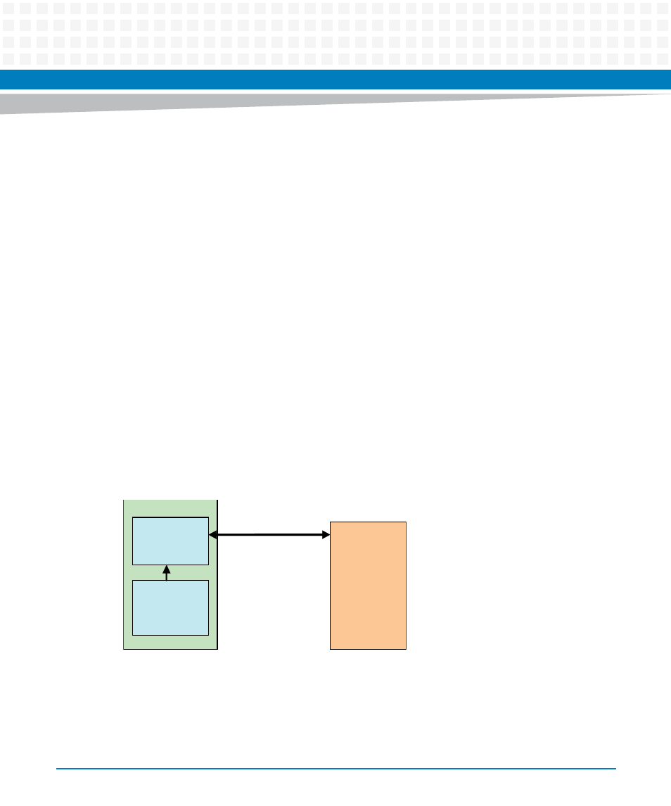
Figure 8-6
GPP Interrupt Structure handled by Glue FPGA
Glue FPGA
Ibex Peak
SERIRQ
Internal Interrupt
Sources
Interrupt Module