4 connector pin definitions, 1 zone 2, Table 3-2 – Artesyn ATCA-8310 Installation and Use (May 2014) User Manual
Page 62: Zone 2 p20 pin assignment, Table 3-3, Zone 2 p23 pin assignment, Controls, indicators, and connectors
Controls, Indicators, and Connectors
ATCA-8310 Installation and Use (6806800M72E)
62
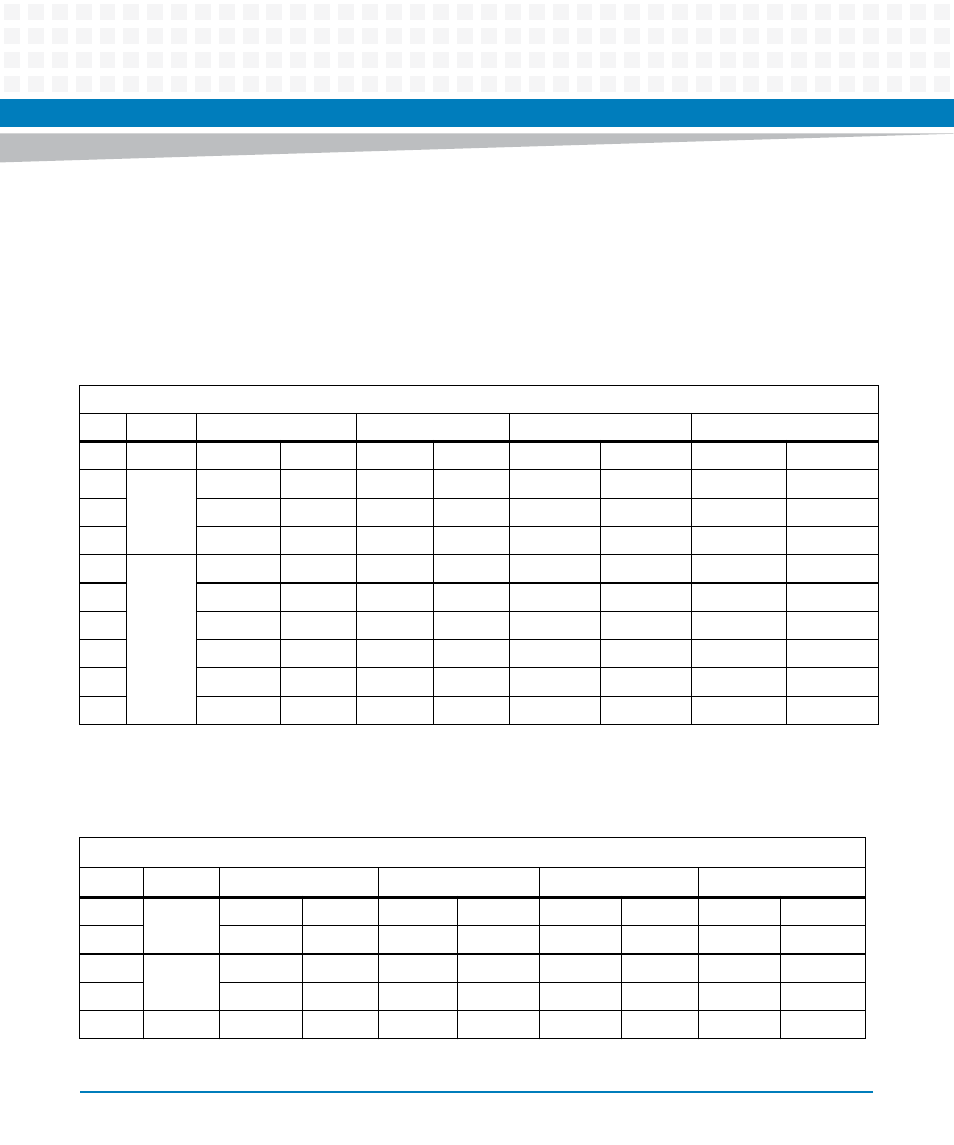
3.4
Connector Pin Definitions
3.4.1
Zone 2
Table 3-2 Zone 2 P20 Pin Assignment
P20
Row # Interface
Col AB
Col CD
Col EF
Col GH
1
CLKs
CLK1A+
CLK1A-
CLK1B+
CLK1B-
CLK2A+
CLK2A-
CLK2B+
CLK2B-
2
Update
Channel
UP-Tx4+
UP-Tx4-
UP-Rx4+
UP-Rx4-
CLK3A+
CLK3A-
CLK3B+
CLK3B-
3
UP-Tx2+
UP-Tx2-
UP-Rx2+
UP-Rx2-
UP-Tx3+
UP-Tx3-
UP-Rx3+
UP-Rx3-
4
UP-Tx0+
UP-Tx0-
UP-Rx0+
UP-Rx0-
UP-Tx1+
UP-Tx1-
UP-Rx1+
UP_Rx1-
5
Reserved
Reserved
NC
Reserved
NC
NC
NC
NC
NC
6
Reserved
Reserved
Reserved
Reserved
Reserved
Reserved
Reserved
Reserved
7
Reserved
NC
NC
NC
Reserved
Reserved
Reserved
Reserved
8
Reserved
Reserved
Reserved
Reserved
Reserved
Reserved
Reserved
Reserved
9
NC
NC
NC
NC
NC
NC
NC
NC
10
NC
NC
NC
NC
NC
NC
NC
NC
Table 3-3 Zone 2 P23 Pin Assignment
P23
Row #
Interface
Col AB
Col CD
Col EF
Col GH
1
Fabric Ch1 FAB1_TX2+ FAB1_TX2- FAB1_RX2+ FAB1_RX2- FAB1_TX3+ FAB1_TX3- FAB1_RX3+ FAB1_RX3-
2
FAB1_TX0+ FAB1_TX0- FAB1_RX0+ FAB1_RX0- FAB1_TX1+ FAB1_TX1- FAB1_RX1+ FAB1_RX1-
3
Fabric Ch0 FAB0_TX2+ FAB0_TX2- FAB0_RX2+ FAB0_RX2- FAB0_TX3+ FAB0_TX3- FAB0_RX3+ FAB0_RX3-
4
FAB0_TX0+ FAB0_TX0- FAB0_RX0+ FAB0_RX0- FAB0_TX1+ FAB0_TX1- FAB0_RX1+ FAB0_RX1-
5
Base 1
B1_TRD1+
B1_TRD1- B1_TRD2+ B1_TRD2-
B1_TRD3+
B1_TRD3- B1_TRD4+
B1_TRD4-