Table 8-213, Debug led register, Table 8-214 – Artesyn ATCA-8310 Installation and Use (May 2014) User Manual
Page 420: Base board and module place identifier, Cpld and fpga, 5 debug led register, 6 base board and module place identifier
CPLD and FPGA
ATCA-8310 Installation and Use (6806800M72E)
420
8.4.2.9.5 Debug LED Register
Address: 0xC4, DebugLedReg
Width: 8 bit
This register controls the condition of the lower 3 LEDs for Debug purposes
8.4.2.9.6 Base Board and Module Place Identifier
Address: 0xC5, BaseIdReg
Width: 8 bit
This register shows the status of the base board module place identifier pins
0
NoMainClkPllLockIntrptMa
sk
RW
0b1:
NoMainClkPllLockIntrptEnab
le, enables NoMainClkPllLock
interrupt generation
0b0
X
X
Table 8-212 Synchronisation and Error Monitor Mask Register (continued)
Bit
Acronym
Type
Description
Default
Pwr
Soft
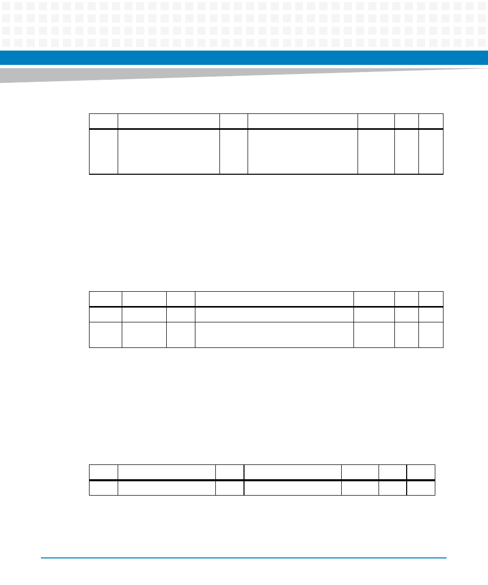
Table 8-213 Debug LED Register
Bit
Acronym
Type
Description
Default
Pwr
Soft
7...3
-
-
reserved
undef
-
-
2...0
DebugLed RW
Debug LED port, a LED is on if the respective
bit is 1
0b000
X
X
Table 8-214 Base Board and Module Place Identifier
Bit
Acronym
Type
Description
Default
Pwr
Soft
7...4
-
-
reserved
undef
-
-