Table 8-112, Supervised telecom clocks reference list, Table 8-111 – Artesyn ATCA-8310 Installation and Use (May 2014) User Manual
Page 320: Telecom clock 166hz control register, Cpld and fpga
CPLD and FPGA
ATCA-8310 Installation and Use (6806800M72E)
320
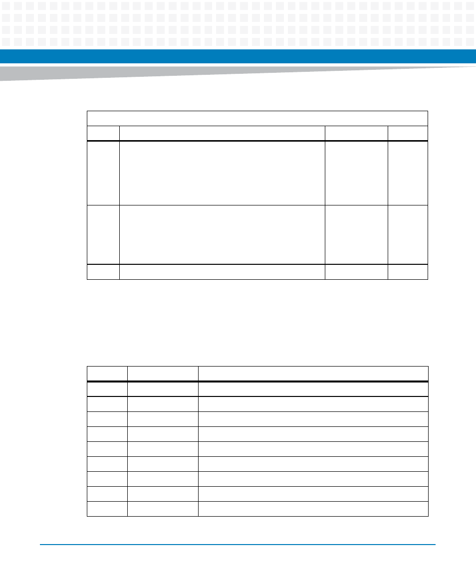
Telecom Clock Monitor Registers
All incoming telecom clock can be monitored and measured in the range from 100 Hz to 100
MHz. Up to 16 different clock inputs may be monitored. See table below.
Table 8-111 Telecom Clock 166Hz Control Register
Address: 0x61
Bit
Description
Default
Access
5:0
Select 0 to 47 phase offset of :
0: No shift
1: 1 x Frame sync period (125 us) shifted
N (2, 3…, 47): N x Frame sync periods (125 us) shifted
48 to 63: Reserved
PWR_GOOD: 0
SPP: r/w
6
ADM Mode:
0: Normal Backplane. Use internal generated 166 Hz. Drive
ADM_MODE_ high
1: ADM Custom Backplane. Use ADM_CLK_166HZ. Drive
ADM_MODE_ low.
PWR_GOOD: 0
SPP: r/w
7
Reserved
0
r
Table 8-112 Supervised Telecom Clocks Reference List
Number
Name
Description
0
CLK1A_IN
Backplane Input Clock CLK1A_IN
1
CLK1B_IN
Backplane Input Clock CLK1B_IN
2
CLK2A_IN
Backplane Input Clock CLK2A_IN
3
CLK2B_IN
Backplane Input Clock CLK2B_IN
4
ADM_CLK_166HZ Backplane Input ClockADM_166Hz
5
CLK_77MHZ_IN
Clock 77MHz from ACS8520
6
CLK_FRSYNC_IN
Clock FRSYNC from ACS8520
7
CLK_T4_IN
Clock T4 from ACS8520
8 - 15
-
Reserved