Table 8-68, User led control register, Cpld and fpga – Artesyn ATCA-8310 Installation and Use (May 2014) User Manual
Page 296: 4 user led control register
CPLD and FPGA
ATCA-8310 Installation and Use (6806800M72E)
296
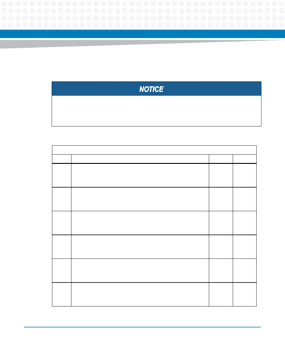
8.2.2.3.4 User LED Control Register
User LED 1 and 2 belong to GPP and User LED 3 and 4 belong to SPP.
The front blade overlay labels USR LED 1 and USR LED 2 correspond to signals LED3_GR_,
LED3_RD_, LED4_GR_, and LED4_RD_. The front blade overlay labels USR LED 3 and USR
LED 4 correspond to signals LED1_GR_, LED1_RD_, LED2_GR_, and LED3_RD_.
Table 8-68 User LED Control Register
Address: 0x05
Bit Description
Default
Access
0
Control green LED output Signal LED1_GR_:
0: LED1_GR_ is driven high.
1: LED1_GR_ is driven low.
0
GPP: r/w
SPP: r
IPMC: r
1
Control green LED output Signal LED1_RD_:
0: LED1_RD_ is driven high.
1: LED1_RD_ is driven low.
0
GPP: r/w
SPP: r
IPMC: r
2
Control green LED output Signal LED2_GR_:
0: LED2_GR_ is driven high.
1: LED2_GR_ is driven low.
0
GPP: r/w
SPP: r
IPMC: r
3
Control green LED output Signal LED2_RD_:
0: LED2_RD_ is driven high.
1: LED2_RD_ is driven low.
0
GPP: r/w
SPP: r
IPMC: r
4
Control green LED output Signal LED3_GR_:
0: LED3_GR_ is driven high.
1: LED3_GR_ is driven low.
0
SPP: r/w
GPP: r
IPMC: r
5
Control green LED output Signal LED3_RD_:
0: LED3_RD_ is driven high.
1: LED3_RD_ is driven low.
0
SPP: r/w
GPP: r
IPMC: r