4 pipeline operation – NEC Network Controller uPD98502 User Manual
Page 88
CHAPTER 2 V
R
4120A
88
Preliminary User’s Manual S15543EJ1V0UM
2.3.4 Pipeline operation
The operation of the pipeline is illustrated by the following examples that describe how typical instructions are
executed. The instructions described are six: ADD, JALR, BEQ, TLT, LW, and SW. Each instruction is taken through
the pipeline and the operations that occur in each relevant stage are described.
2.3.4.1 Add instruction (ADD rd, rs, rt)
IF stage
In
Φ1 of the IF stage, the eleven least-significant bits of the virtual access are used to access
the instruction cache. In
Φ2 of the IF stage, the cache index is compared with the page frame
number and the cache data is read out. The virtual PC is incremented by 4 so that the next
instruction can be fetched.
RF stage
During
Φ2, the 2-port register file is addressed with the rs and rt fields and the register data is
valid at the register file output. At the same time, bypass multiplexers select inputs from either
the EX- or DC-stage output in addition to the register file output, depending on the need for an
operand bypass.
EX stage
The ALU controls are set to do an A + B operation. The operands flow into the ALU inputs, and
the ALU operation is started. The result of the ALU operation is latched into the ALU output
latch during
Φ1.
DC stage
This stage is a NOP for this instruction. The data from the output of the EX stage (the ALU) is
moved into the output latch of the DC.
WB stage
During
Φ1, the WB latch feeds the data to the inputs of the register file, which is addressed by
the rd field. The file write strobe is enabled. By the end of
Φ1, the data is written into the file.
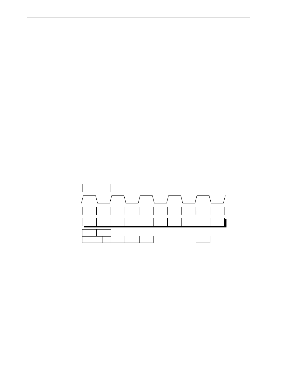
Figure 2-13. ADD Instruction Pipeline Activities (In MIPS III Instruction Mode)
IF1
Cycle
Phase
PCycle
PClock
IF2
Φ2
Φ1
Φ2
Φ1
Φ2
Φ1
Φ2
Φ1
Φ2
Φ1
RF1
RF2
EX1
EX2
DC1
DC2
WB1
WB2
ITLB
IDC
ITC
ICA
IDEC
WB
EX
RF