5 asserting interrupts – NEC Network Controller uPD98502 User Manual
Page 183
CHAPTER 2 V
R
4120A
Preliminary User’s Manual S15543EJ1V0UM
183
2.8.5 Asserting interrupts
2.8.5.1 Detecting hardware interrupts
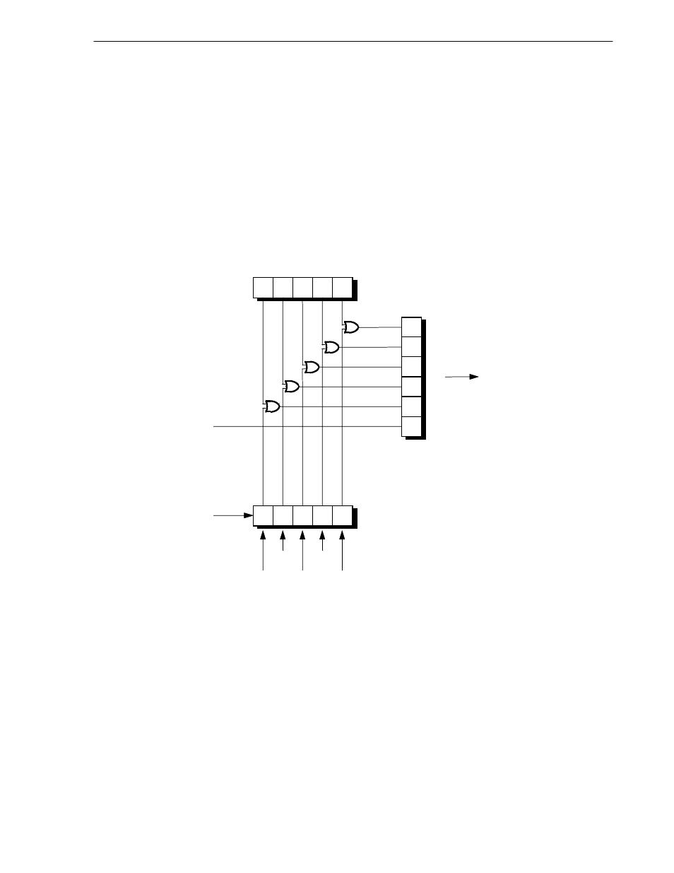
Figure 2-88 shows how the hardware interrupts are readable through the Cause register.
The timer interrupt signal, IP7, is directly readable as bit 15 of the Cause register.
Bits 4 to 0 of the Interrupt register are bit-wise ORed with the current value of the Int4 to 0 signals and the result is
directly readable as bits 14 to 10 of the Cause register.
IP1 and IP0 of the Cause register, which are described in Section 2.5 Exception Processing, are software
interrupts. There is no hardware mechanism for setting or clearing the software interrupts.
Figure 2-88. Hardware Interrupt Signals
IP2
IP3
IP4
IP5
IP6
IP7
10
11
12
13
14
15
0
1
2
3
4
0
1
2
3
4
Cause register
(15:10)
(Internal register)
Interrupt register (4:0)
MasterOut
Timer interrupt
Int4
Int3
Int2
Int1
Int0
See Figure 2-53