10 example of connection – NEC Network Controller uPD98502 User Manual
Page 369
CHAPTER 6 USB CONTROLLER
Preliminary User’s Manual S15543EJ1V0UM
369
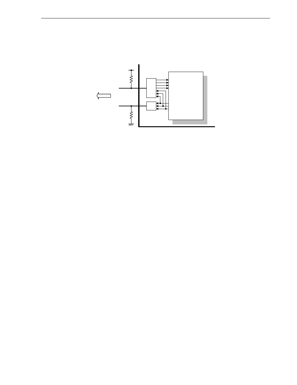
6.10 Example of Connection
USB Controller is connected to the
µPD98502 internal USB I/O buffer as shown in the following Figure 6-32.
Figure 6-32. Example of Connection
O S E
C onnect to
H U B
+3.3 V
A
µ
P D 9 8502
D +
D -
U S B C ontrolle r
D +
B uffe r
O E N
IS E
Y 1
D -
B uffe r
C N B
C N A
1.5 k
Ω
G N D
51 k
Ω
When designing a PCB, it is necessary to connect a 1.5 k
Ω pull-up resistor between the D+ pin and the 3.3 V
power supply to indicate the presence of a full-speed device.
To avoid current floating on the integrated USB Buffer it is recommended to place a 51 k
Ω pull-down resistor
between the D- pin and the GND.
The circuit must be designed such that the
µPD98502 power supply is turned on and off together with the external
3.3 V power supply. If the
µPD98502 power supply is off, but the external 3.3 V power supply is on, the USB HUB
connected to the
µPD98502 will assume that a new device has been connected but, because the µPD98502 power is
off, no response can be returned.
For details of the electrical specifications of the USB, refer to USB Specification 1.1.