2 operations, 1 data read at the power up load, 2 accessing to eeprom – NEC Network Controller uPD98502 User Manual
Page 428
CHAPTER 10 MICRO WIRE
428
Preliminary User’s Manual S15543EJ1V0UM
10.2 Operations
10.2.1 Data read at the power up load
After reset release, power up load processes starts.
In case of the value from EEPROM address 00H is:
1. A5A5H
System Controller sets the EEPROM data (address: 01H to 06H) in the internal registers (MACAR1,
MACAR2, MACAR3).
2. NOT A5A5H
System Controller sets the fix data “0000_0000H” in the internal registers (MACAR1, MACAR2, MACAR3).
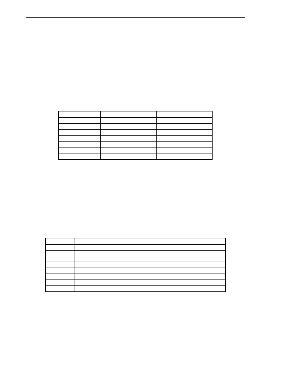
Table 10-1. EEPROM Initial Data
EEPROM Address
Data
Stored Register
00H
A5A5H
-
01H
MAC1 Address data[15:0]
MACAR1[15:0]
02H
MAC1 Address data[31:16]
MACAR1[31:16]
03H
MAC1 Address data[47:32]
MACAR2[15:0]
04H
MAC2 Address data[15:0]
MACAR2[31:16]
05H
MAC2 Address data[31:16]
MACAR3[15:0]
06H
MAC2 Address data[47:32]
MACAR3[31:16]
10.2.2 Accessing to EEPROM
Access to EEPROM starts by writing to the ECCR (EEPROM Command Control Register).
Write command (3 bits) and address (6 bits) of EEPROM into lower 9 bits of ECCR.
There is a difference between write command and read command.
1. Write command
Write data into upper 16 bits of ECCR.
2. Read command
Data is loaded into lower 16bits of ERDR (EEPROM Read Data Register).
Table 10-2. EEPROM Command List
Command
bits 8:6
bits 5:0
Operation
READ
110
A5:A0
Read data from EEPROM assigned by address A5:A0
EWEN
100
11xxxx
Enable Erase/Write command.
This command must be executed before other operating.
ERASE
111
A5:A0
Erase data of EEPROM assigned by address A5:A0
WRITE
101
A5:A0
Write data to EEPROM assigned by address A5:A0
ERAL
100
10xxxx
Erase all data of EEPROM.
WRAL
100
01xxxx
Write all data to EEPROM.
EWDS
100
00xxxx
Disable Erase/Write command.