NEC Network Controller uPD98502 User Manual
Page 336
CHAPTER 6 USB CONTROLLER
336
Preliminary User’s Manual S15543EJ1V0UM
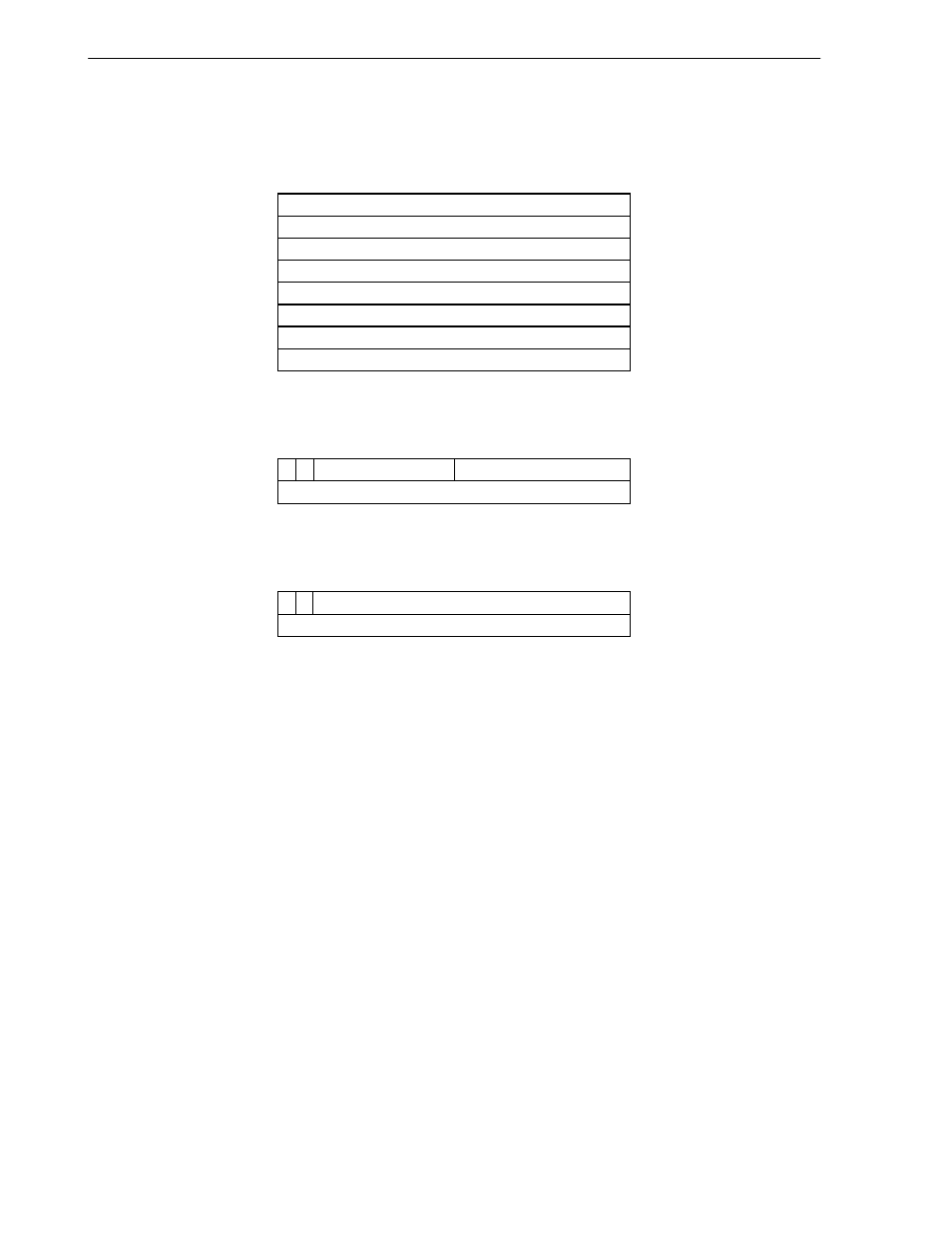
Figure 6-6. Configuration of Transmit Buffer Directory
-T x B uffer D irectory
D irectory Address
-T x Link Pointer
R eserved
31
0
0
B uffer D escriptor N
B uffer D escriptor 4
B uffer D escriptor 3
B uffer D escriptor 2
B uffer D escriptor 1
B uffer D escriptor 0
Link P ointer
-T x B uffer D escriptor
31
0
16 15
B uffer A ddress
L
S ize
|
1
R eserved
30 29
31 30 29
0
0
Tx Buffer Directory:
This is the Tx buffer directory. It contains the buffer descriptor and the link pointer. A
single Tx Buffer Directory can accommodate up to 255 buffer descriptors.
Tx Buffer Descriptor:
This is the Tx buffer descriptor. It maintains the data in the Tx BUFFER.
When Bit 31 (Last bit) is set, the Buffer Descriptor indicates the last buffer in a packet.
Bit30 is used to discriminate between the Buffer Descriptor and Link Pointer. When set to
1, this bit indicates the Buffer Descriptor.
The "Size" field indicates the buffer size. As the buffer size, a value between 1 and 65535
bytes can be set. The "Buffer Address" field indicates the start address of the buffer.
Tx Link Pointer:
This is the link pointer. It points to the next packet directory.
Bit31 is usually set to 0.
Bit30 is used to discriminate between the Buffer Descriptor and Link Pointer. When set to
0, this bit indicates the Link Pointer.
The "Directory Address" field indicates the start address of the next Buffer Directory.