2 block diagram of atm cell processor, Atm cell processor – NEC Network Controller uPD98502 User Manual
Page 230
CHAPTER 4 ATM CELL PROCESSOR
230
Preliminary User’s Manual S15543EJ1V0UM
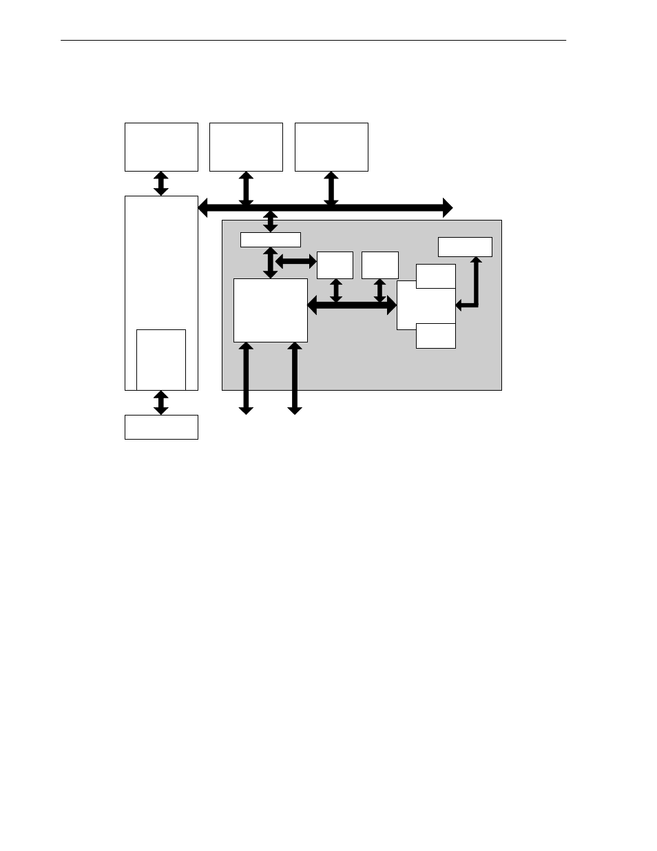
4.1.2 Block diagram of ATM cell processor
Figure 4-1. Block Diagram of ATM Cell Processor
ATM Cell Processor
V
R
4120A RISC
Processor
System
Controller
Ethernet
Controller
#1, #2
USB
Controller
UTOPIA BUS
Controller
RISC Core
SAR
REGS
Work
RAM
Data
RAM
I cache
IRAM
SDRAM
I/F
IBUS
UTOPIA
Level2
UTOPIA
MGR
IBUS I/F
SDRAM
Peripherals
This block is an ATM cell processor. It consists of a 32-bit MCU, Peripherals (Interrupt Controller, Cell Timer,
Scheduling Table and Rx Lookup Table), DMA controllers, a Work-RAM, and SAR-Registers.
4.1.2.1 RISC core
This block is RISC micro-controller. Its features are as follows:
• High performance 32-bit RISC micro-controller, 76 MIPS @ 66 MHz
• 32 x 32-bit General Purpose Registers
• 32-bit ALU, 32-bit Shifter, 16 x 16 Multiply-Adder
• 1-KB Data RAM, 8-KB Instruction RAM, 8-KB Instruction Cache
4.1.2.2 Peripherals
• Interrupt Controller (INTC) and Interrupt Edge Detector (INTEDGE)
• Peripherals for ATM functions – Scheduling Table, Rx Lookup Table, and Cell Timer