Chapter 9 timer, 1 overview, 2 block diagram – NEC Network Controller uPD98502 User Manual
Page 424
424
Preliminary User’s Manual S15543EJ1V0UM
CHAPTER 9 TIMER
9.1 Overview
There are two Timers. The timers are clocked at the system clock rate. All two timers are read/writeable by the
CPU. Timers can be read by the CPU while they are counting. They can be automatically reloaded with the “Timer Set
Count Register” value and restarted. Two timers issues interrupt to the CPU upon reaching their maximum value, the
interrupts can be enabled/disabled.
The TM0IS and TM1IS fields in the Interrupt Status Register “S_ISR” indicate the end of timer count, when set
indicate there is a timer event that completed. All timers count down. The read-write registers “TM0CSR” or
“TM1CSR” have different offset from the read register so write registers are not affected while a value is read from the
read registers “TM0CCR”/”TM1CCR” which indicate a running count of the timer/counter at a given time. Once a value
is loaded in the TM0CSR/TM1CSR, it stays there until Timer’s interrupts are cleared in the Interrupt Status Register
“S_ISR”. The original value can be reloaded in the counter to restart it from that count if Timer CH0/CH1 reload enable
bit is set in the Timer Mode Register “TMMR”. Interrupts are automatically cleared upon CPU reading the Interrupt
Status Register of System Controller “S_ISR”.
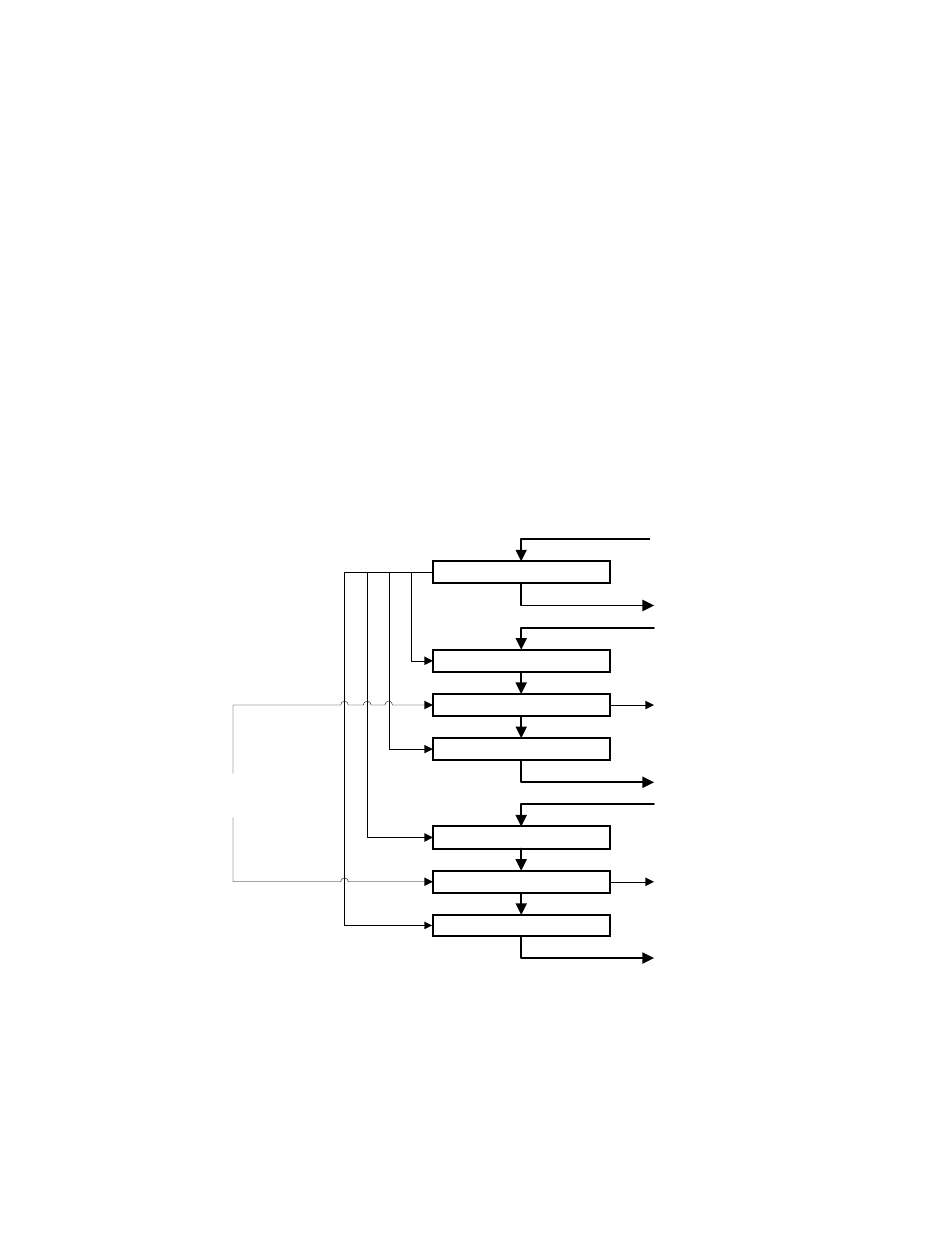
9.2 Block Diagram
to S _ IS R
T M 0 C S R
T M 1 C S R
T M 0 C C R
T M 1 C C R
C H 0 D O W N C O U N T E R
T M M R
C H 1 D O W N C O U N T E R
to S _ IS R
to C P U
fro m C P U
fro m C P U
to C P U
fro m C P U
to C P U
C P U C lo c k
1 0 0 M H z /6 6 M H z