12 uartmsr (uart modem status register), 13 uartscr (uart scratch register) – NEC Network Controller uPD98502 User Manual
Page 423
CHAPTER 8 UART
Preliminary User’s Manual S15543EJ1V0UM
423
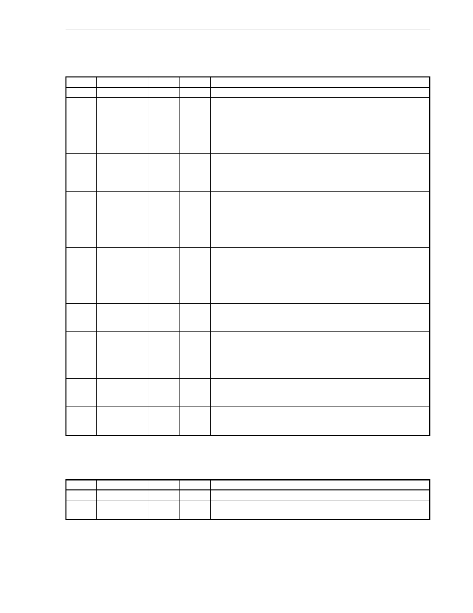
8.3.12 UARTMSR (UART Modem Status Register)
This register reports the current state of and changes in various control signals.
Bits
Field
R/W
Default
Description
31:8
Reserved
R/W
0
Hardwired to 0.
7
DCD
R/W
0
Data Carrier Detect.
1 =URDCD_B state active.
0 = URDCD_B state inactive.
This bit is the complement of the URDCD_B input signal. If the LOOP bit in
the UART Modem Control Register (UARTMCR), is set to 1, the DCD bit is
equivalent to the OUT2 bit in the UARTMCR.
6
RI
R/W
0
Ring Indicator.
1 = not valid.
0 = always reads 0.
This bit has no associated external signal.
5
DSR
R/W
0
Data Set Ready.
1 = URDSR_B state active.
0 = URDSR_B state inactive.
This bit is the complement of the URDSR_B input signal. If the LOOP bit in
the UART Modem Control Register (UARTMCR), is set to 1, the DSR bit is
equivalent to the DTR bit in the UARTMCR.
4
CTS
R/W
0
Clear To Send.
1 =URCTS_B state active.
0 = URCTS_B state inactive.
This bit is the complement of the URCTS_B input signal. If the LOOP bit in
the UART Modem Control Register (UARTMCR), is set to 1, the CTS bit is
equivalent to the RTS bit in the UARTMCR.
3
DDCD
R/W
0
Delta Data Carrier Detect.
1 = URDCD_B state changed since this register was last read.
0 = no such change.
2
TERI
R/W
0
Trailing Edge Ring Indicator.
1 = RI_B state changed since this register last read.
0 = no such change.
RI_B is not implemented as an external signal, so this bit is never set by the
controller.
1
DDSR
R/W
0
Delta Data Set Ready.
1 = URDSR_B input signal changed since this register was last read.
0 = no such change.
0
DCTS
R/W
0
Delta Clear To Send.
1 = URCTS_B state changed since this register was last read.
0 = no such change.
8.3.13 UARTSCR (UART Scratch Register)
This register contains a UART reset bit plus 8 bits of space for any software use.
Bits
Field
R/W
Default
Description
31:8
Reserved
R/W
0
Hardwired to 0.
7:0
USCR
R/W
-
UART Scratch Register.
Available to software for any purpose.