3 usb attachment sequence, H ost p c – NEC Network Controller uPD98502 User Manual
Page 330
CHAPTER 6 USB CONTROLLER
330
Preliminary User’s Manual S15543EJ1V0UM
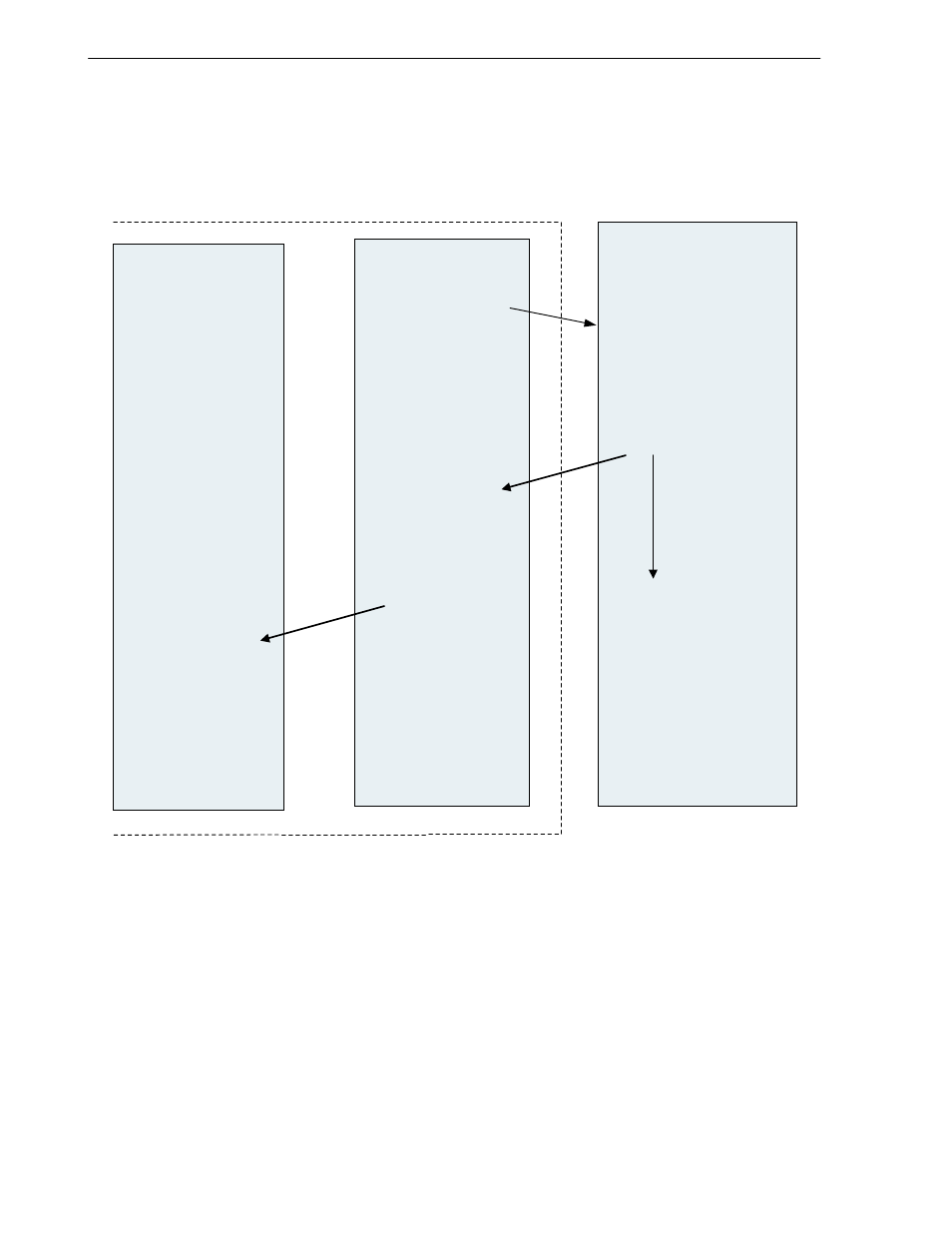
6.3 USB Attachment Sequence
This section describes the sequence that is followed when the
µPD98502 is attached to a USB hub.
Figure 6-2. USB Attachment Sequence
V
R
4120A
U S B
C ontroller
C onnect to a H U B
H ost PC resets
the P ort that
the new device
is connected
(1)
C ontinues to issue
reset signalling
for over 10 m s
T he H U B detects that
a new device is
connected
R eceives R eset
S ignaling
It m ak es U R S T bit
in U _G SR 2 register
active
R eads U _G S R 2
register, detects
R eset S ignalling
H ost P C
Issues w arm -reset
to U S B C ontroller.
S tops R eset
S ignaling
S ets initialization to
each register
(4)
(2)
(3)
(8)
(5)
(6)
(7)
(9)
µ
P D 98502
(1) USB port of the
µPD98502 is attached to a HUB.
(2) Notification that a new device (
µPD98502) has been connected to the HUB is posted to a Host PC.
(3) The Host PC issues Reset Signaling to reset the port to which the device has been connected.
(4) Once 10 ms have elapsed, the Host PC halts the issue of the Reset Signaling.
(5) Notification of the Reset Signaling performed by the Host PC is posted to USB Controller.
(6) To post notification of the Reset by the Host PC to the V
R
4120A, the URST bit of the U_GSR2 register is made
active.
(7) The V
R
4120A reads the U_GSR2 register and, upon finding that the URST bit is active, detects that Reset
Signaling has been issued.
(8) To initialize USB Controller, the V
R
4120A has to issue the warm-reset to USB Controller.
(9) Upon the completion of the reset, USB Controller performs initialization by writing a value into each of USB
Controller's internal registers.