NEC Network Controller uPD98502 User Manual
Page 83
CHAPTER 2 V
R
4120A
Preliminary User’s Manual S15543EJ1V0UM
83
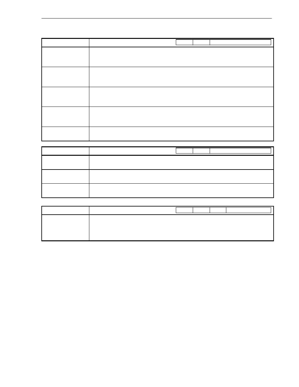
Table 2-21. System Control Coprocessor (CP0) Instructions (2/2)
Instruction
Format and Description
Read Indexed TLB
Entry
TLBR
The TLB entry indexed by the index register is loaded into the entryHi, entryLo0, entryLo1, or page
mask register.
Write Indexed TLB
Entry
TLBWI
The contents of the entryHi, entryLo0, entryLo1, or page mask register are loaded into the TLB entry
indexed by the index register.
Write Random TLB
Entry
TLBWR
The contents of the entryHi, entryLo0, entryLo1, or page mask register are loaded into the TLB entry
indexed by the random register.
Probe TLB For
Matching Entry
TLBP
The address of the TLB entry that matches with the contents of entryHi register is loaded into the index
register.
Return From Exception
ERET
The program returns from exception, interrupt, or error trap.
Instruction
Format and Description
STANDBY
STANDBY
The processor's operating mode is transited from fullspeed mode to standby mode.
SUSPEND
SUSPEND
The processor's operating mode is transited from fullspeed mode to suspend mode.
HIBERNATE
HIBERNATE
The processor's operating mode is transited from fullspeed mode to hibernate mode.
Instruction
Format and Description
Cache Operation
Cache op, offset (base)
The 16-bit offset is sign extended to 32 bits and added to the contents of the register case, to form
virtual address. This virtual address is translated to physical address with TLB. For this physical
address, cache operation that is indicated by 5-bit sub-opcode is performed.
COP0
funct
CO
CACHE
offset
base
op
COP0
funct
CO