2 instruction classes – NEC Network Controller uPD98502 User Manual
Page 67
CHAPTER 2 V
R
4120A
Preliminary User’s Manual S15543EJ1V0UM
67
2.2.2 Instruction classes
The CPU instructions are classified into five classes.
2.2.2.1 Load and store instructions
Load and store are immediate (I-type) instructions that move data between memory and general registers. The
only addressing mode that load and store instructions directly support is base register plus 16-bit signed immediate
offset.
(1) Scheduling a load delay slot
A load instruction that does not allow its result to be used by the instruction immediately following is called a
delayed load instruction. The instruction slot immediately following this delayed load instruction is referred to as
the load delay slot.
In the V
R
4000 Series™, a load instruction can be followed directly by an instruction that accesses a register that is
loaded by the load instruction. In this case, however, an interlock occurs for a necessary number of cycles. Any
instruction can follow a load instruction, but the load delay slot should be scheduled appropriately for both
performance and compatibility with the V
R
Series
microprocessors. For detail, see Section 2.3 Pipeline.
(2) Store delay slot
When a store instruction is writing data to a cache, the data cache is kept busy at the DC and WB stages. If an
instruction (such as load) that follows directly the store instruction accesses the data cache in the DC stage, a
hardware-driven interlock occurs. To overcome this problem, the store delay slot should be scheduled.
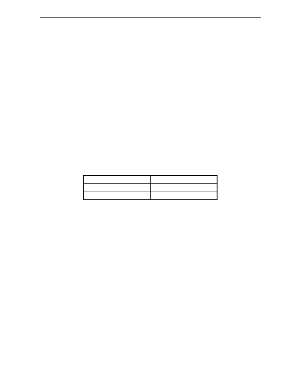
Table 2-2. Number of Delay Slot Cycles Necessary for Load and Store Instructions
Instruction
Necessary Number of Cycles
Load
1
Store
1
(3) Defining access types
Access type indicates the size of a V
R
4120A data item to be loaded or stored, set by the load or store instruction
opcode. Access types and accessed byte are shown in Table 2-3.
Regardless of access type or byte ordering (endianness), the address given specifies the low-order byte in the
addressed field. For a little-endian configuration, the low-order byte is the least-significant byte.
The access type, together with the low-order three bits of the address, defines the bytes accessed within the
addressed doubleword (shown in Table 2-3). Only the combinations shown in Table 2-3 are permissible; other
combinations cause address error exceptions.
Tables 2-4 and 2-5 list the ISA-defined load/store instructions and extended-ISA instructions, respectively.