3 pipeline, 1 pipeline stages – NEC Network Controller uPD98502 User Manual
Page 84
CHAPTER 2 V
R
4120A
84
Preliminary User’s Manual S15543EJ1V0UM
2.3 Pipeline
This section describes the basic operation of the V
R
4120A Core pipeline, which includes descriptions of the delay
slots (instructions that follow a branch or load instruction in the pipeline), interrupts to the pipeline flow caused by
interlocks and exceptions, and CP0 hazards.
2.3.1 Pipeline stages
The pipeline is controlled by PClock(one cycle of PClock which runs at 4-times frequency of MasterClock) and one
cycle of this PClock is called PCycle. Each pipeline stage takes one PCycle.
2.3.1.1 Pipeline in MIPS III instruction mode
The V
R
4120A has a five-stage instruction pipeline; each stage takes one PCycle, and each PCycle has two
phases:
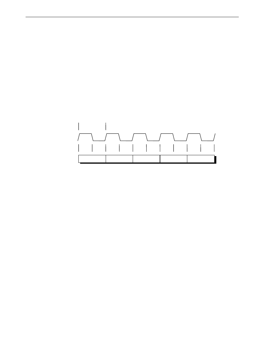
Φ1 and Φ2, as shown in Figure 2-9. Thus, the execution of each instruction takes at least 5 PCycles. An
instruction can take longer - for example, if the required data is not in the cache, the data must be retrieved from main
memory.
Figure 2-9. Pipeline Stages (MIPS III Instruction Mode)
Cycle
Phase
PCycle
PClock
IF
Φ2
Φ1
Φ2
Φ1
Φ2
Φ1
Φ2
Φ1
Φ2
Φ1
RF
EX
DC
WB
The five pipeline stages are:
IF - Instruction cache fetch
RF - Register fetch
EX - Execution
DC - Data cache fetch
WB - Write back
Figure 2-10 shows the five stages of the instruction pipeline. In this figure, a row indicates the execution process of
each instruction, and a column indicates the processes executed simultaneously.