NEC Network Controller uPD98502 User Manual
Page 118
CHAPTER 2 V
R
4120A
118
Preliminary User’s Manual S15543EJ1V0UM
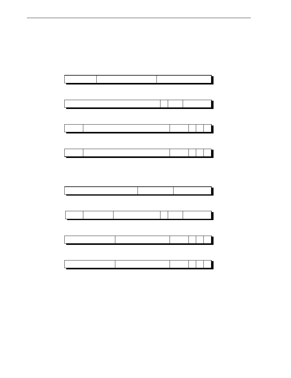
2.4.4.1 Format of a TLB entry
Figure 2-33 shows the TLB entry formats for both 32- and 64-bit modes. Each field of an entry has a corresponding
field in the EntryHi, EntryLo0, EntryLo1, or PageMask registers.
Figure 2-33. Format of a TLB Entry
114
115
96
127
107 106
(a) 32-bit mode
0
MASK
0
8
2
1
21
13
8
11
64
95
75
74 73 72
71
VPN2
G
0
ASID
59
60
22
4
32
63
37
38
35 34 33
0
PFN
C
D
V
0
1
3
1
1
27
28
22
4
0
31
5
6
3
2
1
0
PFN
C
D
V
0
1
3
1
1
210
211
192
255
203 202
(b) 64-bit mode
0
MASK
0
190 189
8
2
1
2
22
29
45
8
11
128
191
139 138 137 136 135
R
0
VPN2
G
0
ASID
91
92
22
36
64
127
69
70
67 66 65
0
PFN
C
D
V
0
1
3
1
1
27
28
22
36
0
63
5
6
3
2
1
0
PFN
C
D
V
0
1
3
1
1
167
168
The format of the EntryHi, EntryLo0, EntryLo1, and PageMask registers are nearly the same as the TLB entry.
However, it is unknown what bit of the EntryHi register corresponds to the TLB G bit.