2 internal block diagram, S ie e p c – NEC Network Controller uPD98502 User Manual
Page 310
CHAPTER 6 USB CONTROLLER
310
Preliminary User’s Manual S15543EJ1V0UM
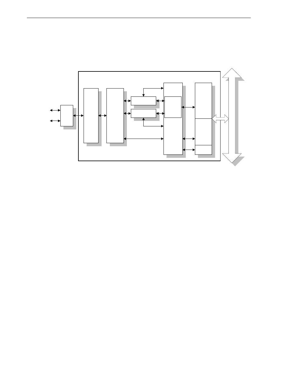
6.1.2 Internal block diagram
USB Controller internal block diagram is as shown below.
Figure 6-1. USB Controller Internal Configuration
S IE
E P C
IB U S
D +
D -
U S B
B U S I/F
R x FIFO
M aster
I/F
S lav e
I/F
I/O
B uf
s lave
decoder
T x FIFO
D M A C
M C O N T
U S B C O N TR O L LE R
USB Controller's configuration features the following blocks.
SIE (Serial Interface Engine): Performs Serial/Parallel conversion, NRZI encoding/decoding, CRC calculation,
etc.
EPC (EndPoints Controller): Performs data transmission/reception for each Endpoint.
Tx FIFO (Transmit FIFO):
FIFO for transmitting data
Rx FIFO (Receive FIFO):
FIFO for receiving data
MCONT (Main Controller):
Block for controlling transmission and reception.
DMAC (DMA Controller):
Block for controlling DMA transfer.
Master_if (Master Interface): Master section of the Internal BUS interface.
Slave_if (Slave Interface):
Slave section of the Internal BUS interface.
I/O Buf (I/O Buffer):
I/O buffer that satisfies the electrical specifications of the USB.
Internal BUS:
The internal bus of the
µPD98502.