18 a_t1r (t1 time register), 19 a_tsr (time stamp register), 20 a_ibbar (ibus base address register) – NEC Network Controller uPD98502 User Manual
Page 245: 21 a_inbar (instruction base address register)
CHAPTER 4 ATM CELL PROCESSOR
Preliminary User’s Manual S15543EJ1V0UM
245
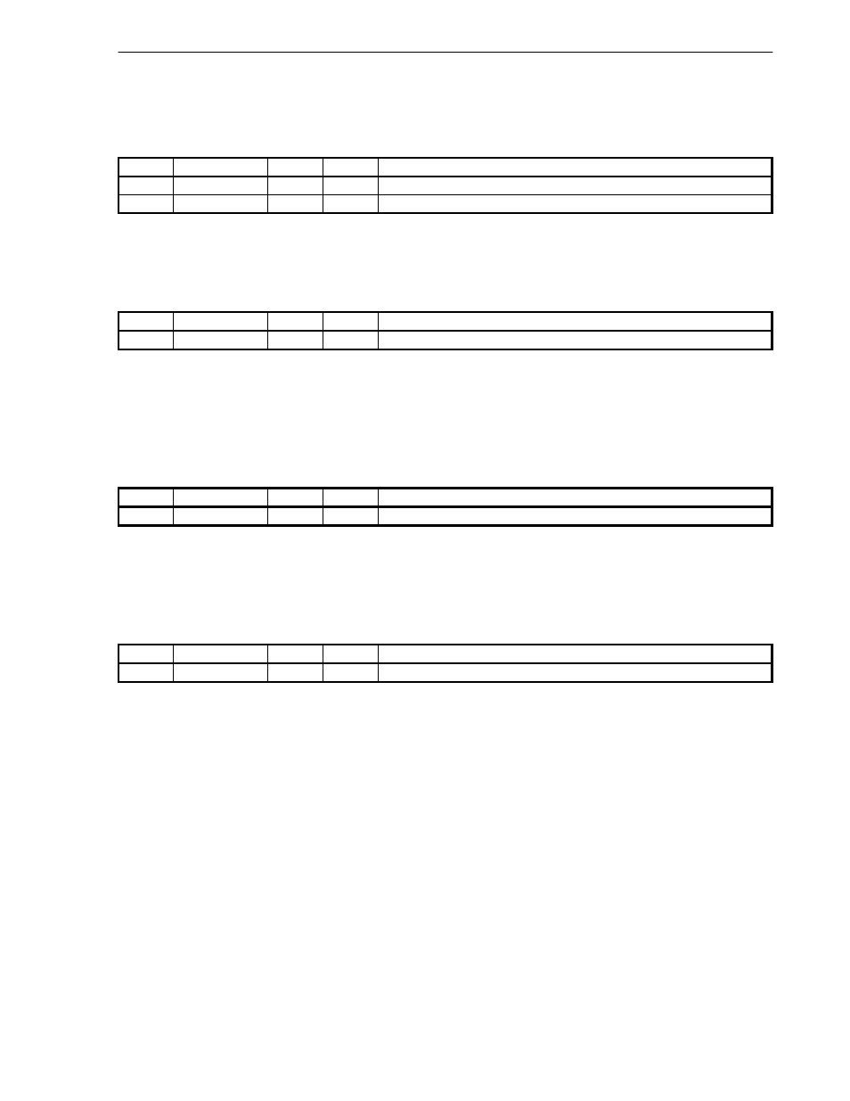
4.4.18 A_T1R (T1 Time Register)
A_T1R shows time which user allows ATM Cell Processor to spend to receive a whole of one packet. Initial value
is “0000_FFFFH”.
Bits
Field
R/W
Default
Description
31
Reserved
R/W
0
Reserved for future use. Write ‘0’s.
30:0
A_T1R
R/W
FFFFH
Allowable time to receive a whole of one packet
4.4.19 A_TSR (Time Stamp Register)
A_TSR shows a value of the 32-bit counter that ATM Cell Processor counts its system clock. It is used as time
stamps of receive start time of T1 timer function. Initial value is “0000_0000H”, and count up starts right after reset.
Bits
Field
R/W
Default
Description
31:0
A_TSR
R/W
0
System clock count of ATM Cell Processor
4.4.20 A_IBBAR (IBUS Base Address Register)
A_IBBAR contains the base address for the access thorough IBUS to outside. RISC Core-space is addressed
using 24-bit address, while V
R
4120A RISC Processor space is addressed using 32-bit address. Therefore, the
extension of address is necessary when the access from the inside of this block to the outside is requested. Initial
value is zero.
Bits
Field
R/W
Default
Description
31:0
A_IBBAR
R/W
0
Base address for the access thorough IBUS to outside
4.4.21 A_INBAR (Instruction Base Address Register)
A_INBAR contains the base address to fetch instructions. RISC Core-space is addressed using 24-bit address,
while V
R
4120A RISC Processor space is addressed using 32-bit address. Therefore, the extension of address is
necessary when the access from the inside to the outside is requested. Initial value is zero.
Bits
Field
R/W
Default
Description
31:0
A_INBAR
R/W
0
Base address to fetch instructions