3 reset output, 4 interrupt input – NEC Network Controller uPD98502 User Manual
Page 389
CHAPTER 7 PCI CONTROLLER
Preliminary User’s Manual S15543EJ1V0UM
389
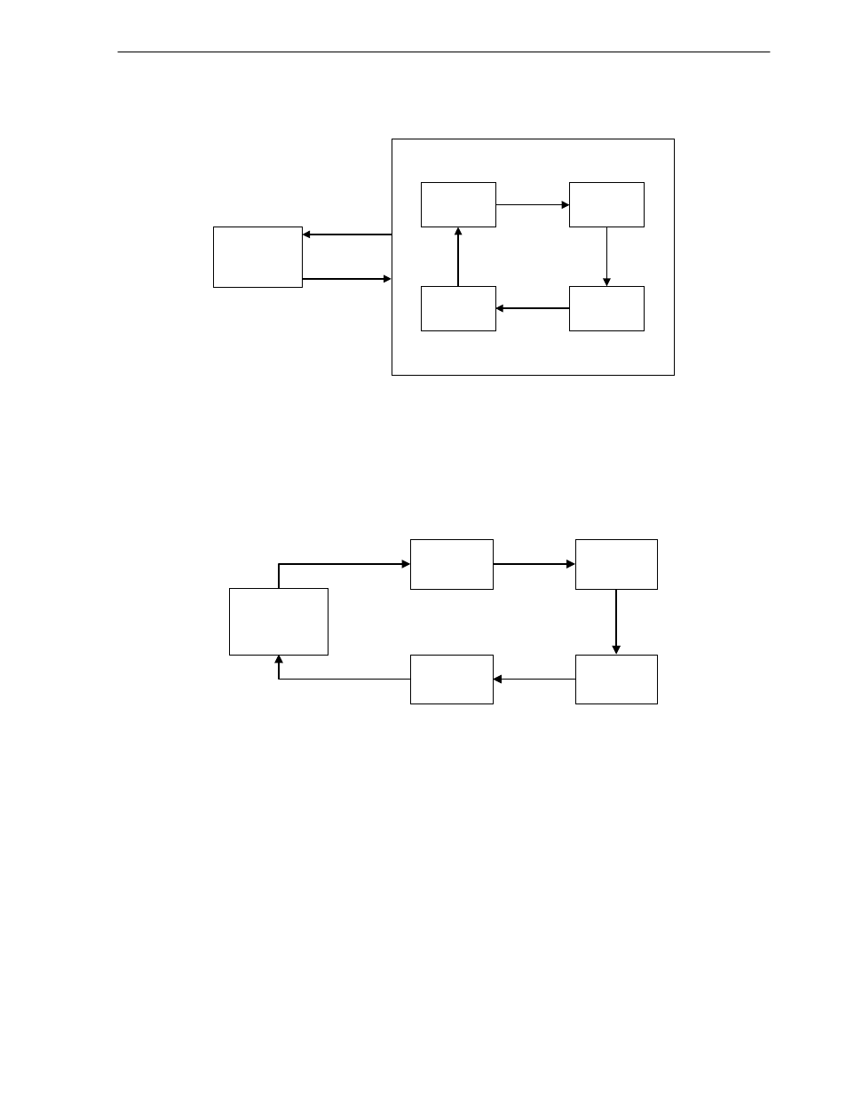
Figure 7-16. Arbitration in Alternating Mode
P C I
C ontrolle r
G N T #0
G N T #3
G N T #1
G N T #2
R ota tin g
A lterna ting
7.4.2.2 Rotating mode
Priority rotates among all PCI master devices including the PCI Controller in this mode.
When all REQ_B input signals to this arbiter go up to high, which means no device issues the acquisition of PCI
bus, this arbiter gives the right of use of PCI bus to the device that had acquired PCI bus last as arbitration parking.
Figure 7-17. Arbitration in Rotating Mode
P C I
C ontroller
G N T #0
G N T #3
G N T #1
G N T #2
R otating
7.4.3 Reset output
In Host mode, the PCI Controller asserts reset signal for PCI bus, when PRSTO bit in P_HMCR register is set to a
“1”. In order to deassert the signal, the V
R
4120A should reset PRSTO bit to a “0”.
7.4.4 Interrupt input
The PCI Controller has an interrupt input port and the SERR_B input port so as to receive interrupts and SERR_B
from PCI-devices.
If any of PCI interrupts is asserted, PINTR bit in P_IGSR register is set and the PCI Controller issues an interrupt to
the V
R
4120A (if not masked). The PCI Controller handles the interrupt input port in “level sensitive” way.
If SERR_B comes, PSERI bit in P_IGSR register is set and the PCI Controller issues an interrupt to the V
R
4120A
(if not masked). The PCI Controller handles SERR_B input in “edge sensitive” way.
The PCI Controller has only 1 port for interrupt input and SERR_B input each, so the interrupt or SERR_B from
PCI devices should be combined, in wire-ORed way for example, on the board.