9 loopback mode – NEC Network Controller uPD98502 User Manual
Page 368
CHAPTER 6 USB CONTROLLER
368
Preliminary User’s Manual S15543EJ1V0UM
6.9 Loopback Mode
USB Controller features a built-in loopback function for test purposes.
To enable the loopback function, set the LE bit (Bit 1) of the USB General Mode Register to 1.
Once the loopback function has been activated, USB Controller gets the data from system memory and places it
into the Tx FIFO. The data is returned by the EndPoint Controller. The returned data is written into the Rx FIFO, after
it is returned to system memory.
Transmitting and receiving should be performed using the normal settings. The Tx and Rx indications are issued as
normal.
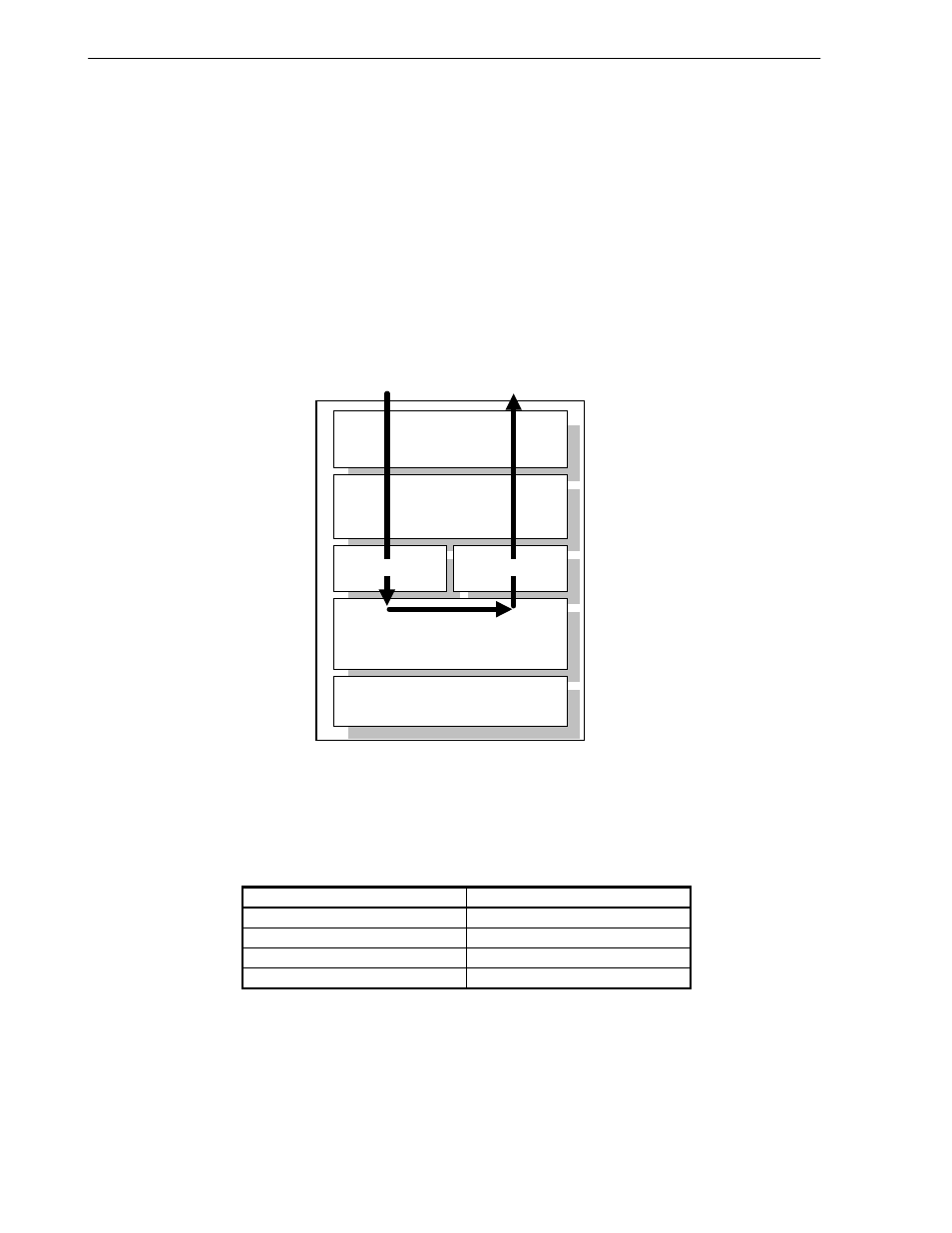
The internal data flow is as shown below.
Figure 6-31. Data Flow in Loopback Mode
IB U S I/F
C ontroller
T x data
R x data
E P C ontroller
S IE
T x F IF O
R x F IF O
As shown in the figure, in loopback mode data reception from the USB and data transmission to the USB are not
performed. All data is returned by the EndPoint Controller.
Following table indicates the Endpoint which is used to transmit data and the Endpoint at which the data will be
received.
Tx EndPoint
Rx EndPoint
EndPoint0 (Control)
EndPoint0 (Control)
EndPoint1 (Isochronous)
EndPoint2 (Isochronous)
EndPoint3 (Bulk)
EndPoint4 (Bulk)
EndPoint5 (Interrupt)
EndPoint6 (Interrupt)