4 system control interface – NEC Network Controller uPD98502 User Manual
Page 38
CHAPTER 1 INTRODUCTION
38
Preliminary User’s Manual S15543EJ1V0UM
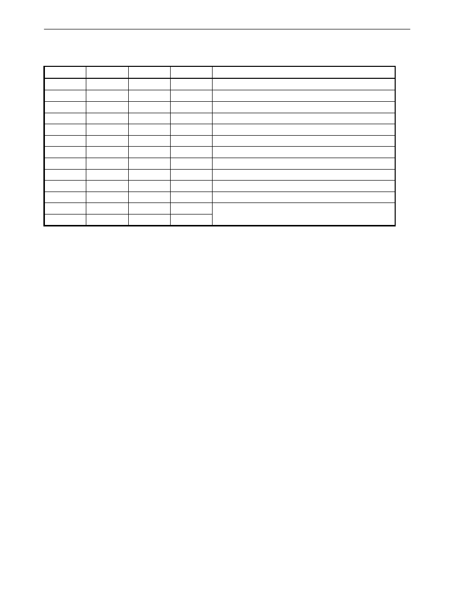
1.7.4 System control interface
Pin Name
Pin No.
I/O
Active Level
Function
SCLK
V1
I
System clock (33 MHz)
CLKSL
U1
I
Clock select (100 MHz/66 MHz)
PSMD
AA3
I
System PLL mode control (0: normal, 1: through)
PSTBY
AA2
I
System PLL standby mode control (0: active, 1: standby)
PUMD
B27
I
USB PLL mode control (0: normal, 1: through)
PUSTBY
D25
I
USB PLL standby mode control (0: active, 1: standby)
BIG
D16
I
H
V
R
4120 big endian mode
ENDCEN
C15
I
Endian conversion enable
EXINT_B
A15
I
L
External interrupt
EXNM_BI
A13
I
L
External non-maskable interrupt
RSTB_B
AB30
I
L
System reset
RMSL0
E11
I
ROM access bus width select
RMSL1
B11
I
(RMSL1/0 = L/L: 32-bit, L/H: 16-bit, H/L: 8-bit)