3 remote wake up – NEC Network Controller uPD98502 User Manual
Page 366
CHAPTER 6 USB CONTROLLER
366
Preliminary User’s Manual S15543EJ1V0UM
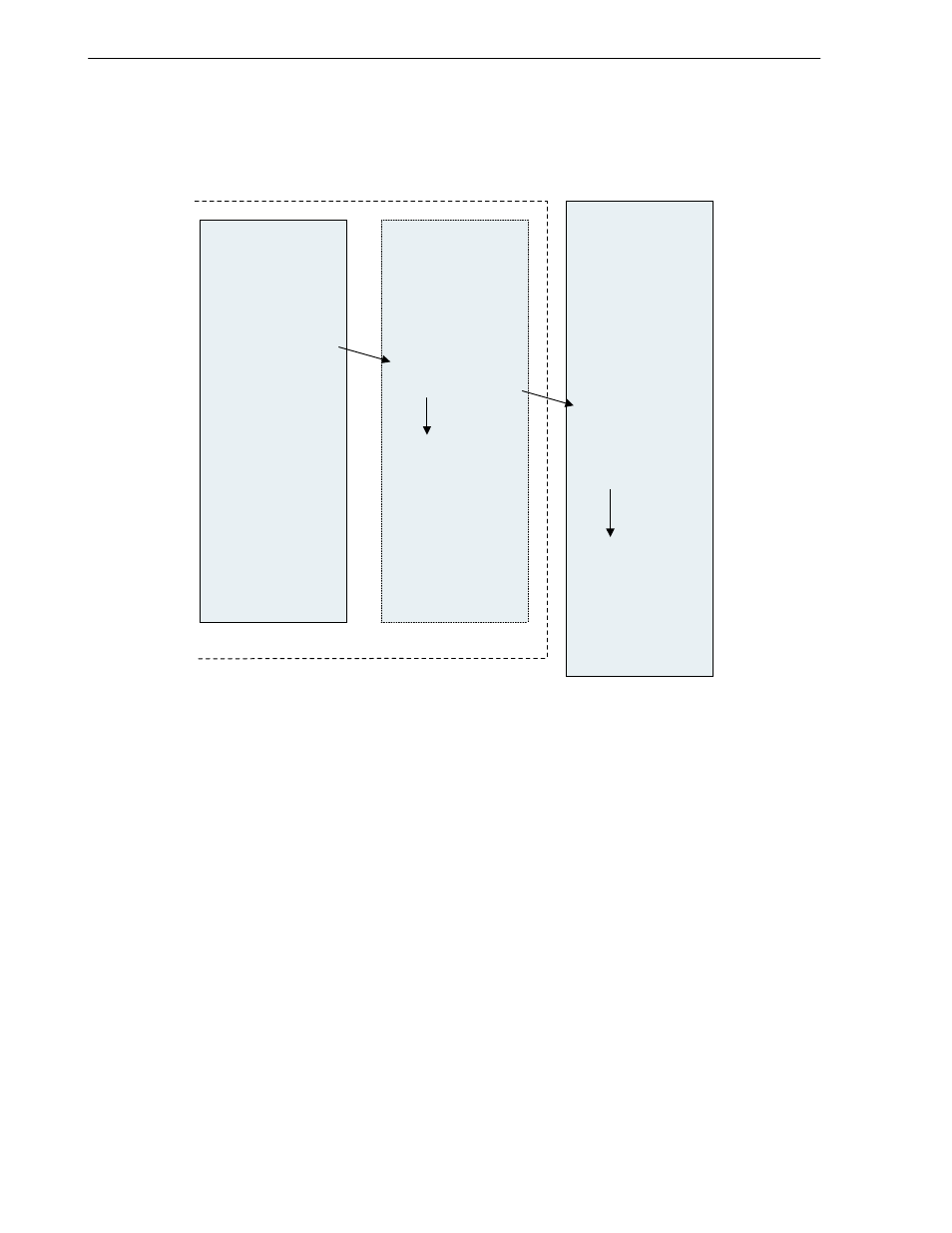
6.7.3 Remote wake up
The Remote Wake Up sequence is shown below.
Figure 6-29. Remote Wake Up Sequence
V
R
4120A
U S B
C ontroller
H ost P C
R eceive s the
data from
S ets R R bit (Bit0 )
in U S B G eneral
M o de R eg iste r
S tarts K -sta te
signa lin g
20 m s
10 m s
(1 )
(2 )
S tops K -sta te
signa lin g
(4 )
(5 )
D etects K-state
signa lin g.
S tarts to
broadcast
R E SU M E sign aling
(6 )
S tops R E S U M E
signa lin g.
E xecutes E O P
signa lin g for only
2 b it-tim e
(7 )
E nd p rocessing
of R em o te W ak e
U p
(8 )
S ets send ing
D ata to U S B
(3 )
µ
P D 98502
oth er blo ck
(1) Here, it is assumed that the USB is in the Suspend status. Data is received from other block.
(2) The V
R
4120A sets the RR bit (Bit 0) of the USB General Mode Register in order to switch the USB in the
Suspend status to the Resume status.
(3) Once the RR bit of the USB General Mode Register has been set, USB Controller starts K-state Signaling for
the USB.
(4) The V
R
4120A can continue to set transmit data for the USB. Specifically, the V
R
4120A prepares transmit data
in system memory, then writes data into the USB Command Register (Address: 1000_1040H) and the USB
Command Extension Register (Address: 1000_1044H).
(5) USB Controller continues K-state Signaling for 5 ms, then terminates the signaling.
(6) The Host PC, upon receiving the K-state Signaling, broadcasts RESUME signaling. This RESUME signaling
continues for a minimum of 20 ms.
(7) Once at least 20 ms have elapsed, the Host PC terminates RESUME Signaling, then issues EOP Signaling for
a 2 bit-time duration.
(8) As a result of this sequence, Remote Wake Up is terminated, and the transaction being performed by the USB
is restarted.