Hdlc mode register (fpsmr) -8, Fpsmr field descriptions -8, The fpsmr þelds are described in table 31-6 – Motorola MPC8260 User Manual
Page 910
31-8
MPC8260 PowerQUICC II UserÕs Manual
MOTOROLA
Part IV. Communications Processor Module
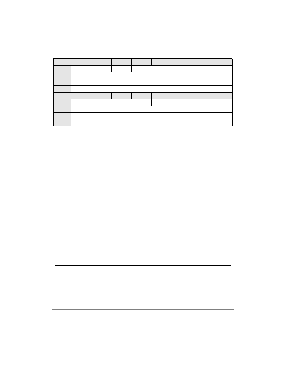
The FPSMR Þelds are described in Table 31-6.
Bits
0
1
2
3
4
5
6
7
8
9
10
11
12
13
14
15
Field
NOF
FSE
MFF
Ñ
TS
Ñ
Reset
0000_0000_0000_0000
R/W
R/W
Addr
0x11304 (FPSMR1), 0x11324 (FPSMR2), 0x11324 (FPSMR3)
Bits
16
17
18
19
20
21
22
23
24
25
26
27
28
29
30
31
Field
NBL
Ñ
CRC
Ñ
Reset
0000_0000_0000_0000
R/W
R/W
Addr
0x11306 (FPSMR1), 0x11326 (FPSMR2), 0x11326 (FPSMR3)
Figure 31-3. HDLC Mode Register (FPSMR)
Table 31-6. FPSMR Field Descriptions
Bits
Name
Description
0Ð3
NOF
Number of ßags. Minimum number of ßags between or before frames (0Ð15 ßags). If NOF = 0000, no
ßags are inserted between the frames. Thus, for back-to-back frames, the closing ßag of one frame is
immediately followed by the opening ßag of the next frame.
4
FSE
Flag sharing enable. This bit is valid only if GFMR[RTSM] is set.
0 Normal operation
1 If NOF = 0000, a single shared ßag is transmitted between back-to-back frames. Other values of
NOF are decremented by 1 when FSE is set. This is useful in signaling system #7 applications.
5
MFF
Multiple Frames in FIFO
0 Normal operation. The transmit FIFO buffer must never contain more than one HDLC frame. The
CTS lost status is reported accurately on a per-frame basis. The receiver is not affected by this bit.
1 The transmit FIFO buffer can contain multiple frames, but lost CTS is not guaranteed to be
reported on the exact buffer/frame it occurred on. This option, however, can improve the
performance of HDLC transmissions for small back-to-back frames or if the user prefers to
strongly limit the number of ßags sent between frames. MFF does not affect the receiver.
7Р8
С
Reserved, should be cleared.
9
TS
Time stamp
0 Normal operation.
1 A 32-bit time stamp is added at the beginning of the receive BD data buffer, thus the buffer pointer
must be (32-byte aligned - 4). The BDÕs data length does not include the time stamp. See
Section 13.3.7, ÒRISC Time-Stamp Control Register (RTSCR).У
10Р15
С
Reserved, should be cleared.
16
NBL
0 nibble mode disabled (1 bit of data per clock).
1 nibble mode (4 bits of data per clock).
17Р23
С
Reserved, should be cleared.