1 using transmit internal rate mode, Using transmit internal rate mode -92, Aal1 srts clock recovery using external logic -92 – Motorola MPC8260 User Manual
Page 872
29-92
MPC8260 PowerQUICC II UserÕs Manual
MOTOROLA
Part IV. Communications Processor Module
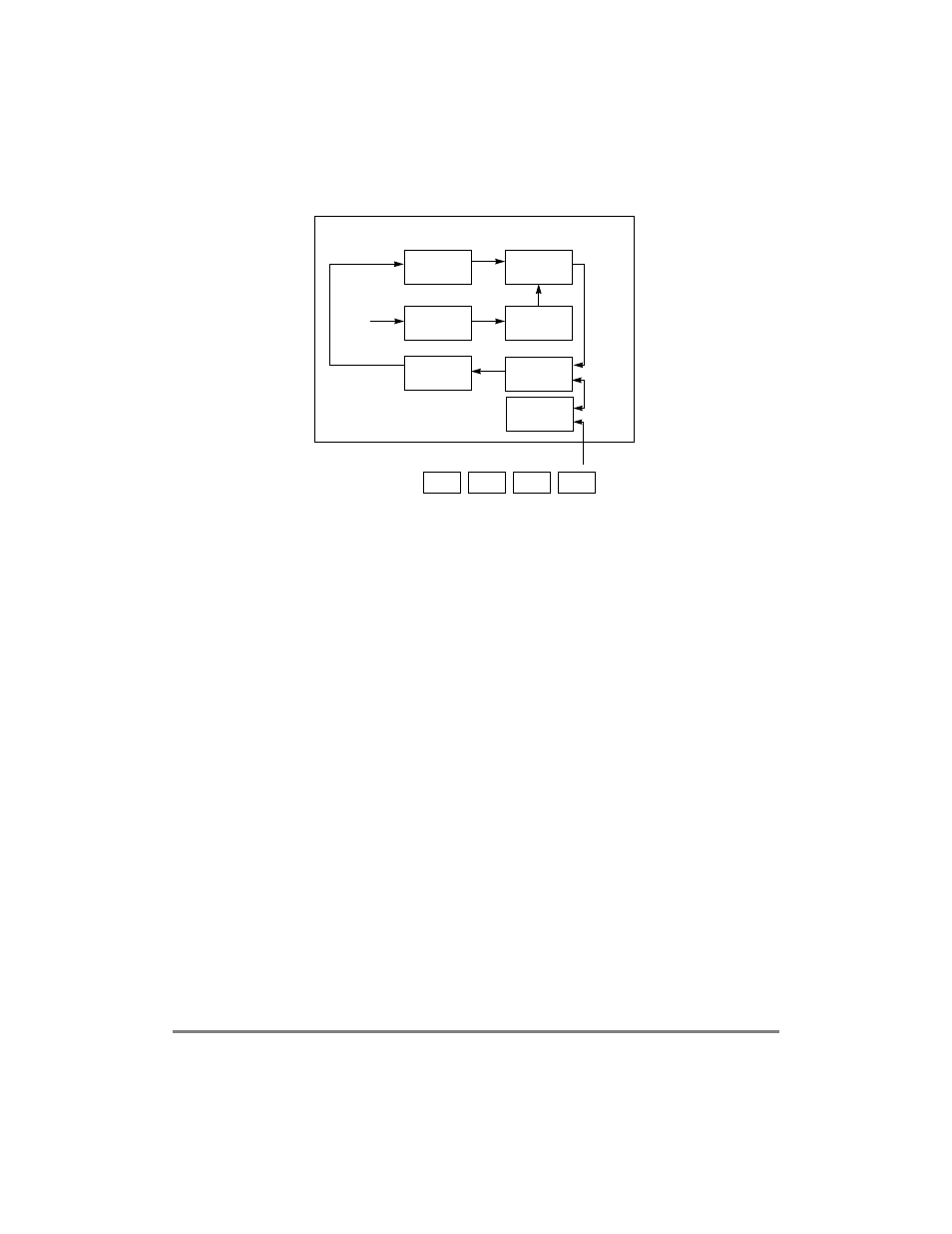
Figure 29-65. AAL1 SRTS Clock Recovery Using External Logic
On every eighth cell, the MPC8260 writes a new SRTS code to the external logic using the
bus selected in RCT[BIB]. The CP writes the SRTS code using a DMA write cycle of 1-
byte data size. Each AAL1 channel can be programmed to select one of 16 addresses
available for writing the SRTS result. The SRTS code is written to the least-signiÞcant
nibble of that address (SRTS[0]=lsb, SRTS[3]=msb). The SRTS is synchronized with the
sequence count cycleÑSRTS[3] is read from the cell with SN = 1 and SRTS[0] is read from
the cell with SN = 7. The SRTS PLL makes periodic clock adjustments based on the
difference between a locally generated SRTS and a remotely generated SRTS retrieved
every eight received cells.
29.16 ConÞguring the ATM Controller for Maximum
CPM Performance
The following sections recommend ATM controller conÞgurations to maximize CPM
performance.
29.16.1 Using Transmit Internal Rate Mode
When the total transmit rate is less than the PHY rate, use the transmit internal rate mode
and conÞgure the internal rate clock to the maximum bit rate required. (See 29.2.1.4,
ÒTransmit External Rate and Internal Rate Modes.Ó) The PHY then automatically Þlls the
unused bandwidth with idle cells, not the ATM controller. If the internal rate mode is not
used, CPM performance is consumed generating the idle cell payload and using the
scheduling algorithm to Þll the unused bandwidth at the higher PHY rate.
p = 4 bit
1/64
155.52 MHz
2.43 MHz (E1/T1)
Latch
fs
Counter
divided by N
(N=3008 bits = 8 SAR PDU)
SRTS
External SRTS Logic
SRTS Diff
+
-
VCO
SN=1
SN=3
SN=5
SN=7
DMA writes new SRTS code
Latch
counter