Scc hdlc receiving using rxbds -10 – Motorola MPC8260 User Manual
Page 618
21-10
MPC8260 PowerQUICC II UserÕs Manual
MOTOROLA
Part IV. Communications Processor Module
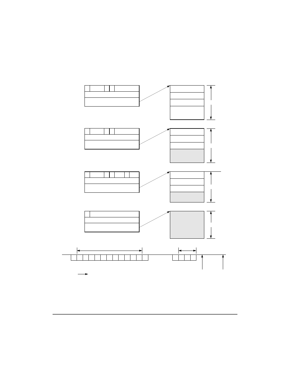
last buffer of a frame contains the total number of frame bytes, including the 2 or 4 bytes
for CRC. Figure 21-5 shows an example of how RxBDs are used in receiving.
Figure 21-5. SCC HDLC Receiving Using RxBDs
Buffer
0
0x0008
32-Bit Buffer Pointer
1
E
F
Receive BD 0
Status
Length
Pointer
0
0x000B
32-Bit Buffer Pointer
0
E
F
Receive BD 1
Status
Length
Pointer
0
0x0003
32-Bit Buffer Pointer
1
E
F
Receive BD 2
Status
Length
Pointer
1
XXXX
32-Bit Buffer Pointer
E
Receive BD 3
Status
Length
Pointer
Address 1
Address 2
Control Byte
Buffer
CRC Byte 1
CRC Byte 2
Buffer
Address 1
Address 2
Buffer
Control Byte
Empty
8 Bytes
8 Bytes
8 Bytes
8 Bytes
Two Frames
Received in HDLC
Unexpected abort
Stored in Rx Buffer
Line Idle
occurs before
Present
time
Time
Stored in Rx Buffer
Buffer full
Buffer closed
when closing flag
Buffer
still empty
1
AB
5
Empty
MRBLR = 8 Bytes for this SCC
Empty
Last I-Field Byte
Information
(I-Field) Bytes
Received
Abort was
received after
control byte
0
L
1
L
1
L
F
A
A
C
I
I
I
I
I
I
CR CR F
closing flag
Abort/Idle
F
A
A
C
Legend:
F = Flag
A = Address byte
C = Control byte
I = Information byte
CR = CRC Byte