2 interrupt controller, Interrupt controller -7, Software watchdog timer block diagram -7 – Motorola MPC8260 User Manual
Page 145
MOTOROLA
Chapter 4. System Interface Unit (SIU)
4-7
Part II. ConÞguration and Reset
Although most software disciplines permit or even encourage the watchdog concept, some
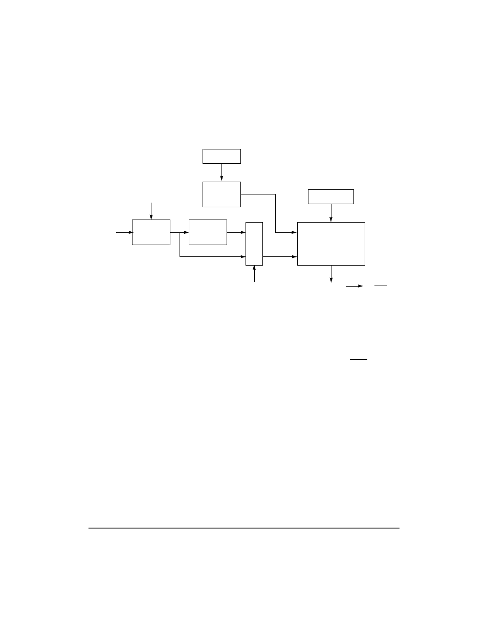
systems require a selection of time-out periods. For this reason, the software watchdog
timer must provide a selectable range for the time-out period. Figure 4-7 shows how to
handle this need.
Figure 4-7. Software Watchdog Timer Block Diagram
In Figure 4-7, the range is determined by SYPCR[SWTC]. The value in SWTC is then
loaded into a 16-bit decrementer clocked by the system clock. An additional divide-by-
2,048 prescaler is used when needed.
The decrementer begins counting when loaded with a value from SWTC. After the timer
reaches 0x0, a software watchdog expiration request is issued to the reset or MCP control
logic. Upon reset, SWTC is set to the maximum value and is again loaded into the software
watchdog register (SWR), starting the process over. When a new value is loaded into
SWTC, the software watchdog timer is not updated until the servicing sequence is written
to the SWSR. If SYPCR[SWE] is loaded with 0, the modulus counter does not count.
4.2 Interrupt Controller
Key features of the interrupt controller include the following:
¥
Communications processor module (CPM) interrupt sources (FCCs, SCCs, MCCs,
timers, SMCs, I
2
C, IDMA, SDMA, and SPI)
¥
Three SIU interrupt sources (PIT and TMCNT)
¥
24 external sources (16 port C and 8 IRQ)
¥
Programmable priority between PIT and TMCNT
¥
Programmable priority between SCCs, FCCs, and MCCs
Disable
Clock
SWR/Decrementer
Time-out
16-Bit
SYPCR[SWTC]
SWE
Service
Logic
Reload
Rollover = 0
Reset
SWSR
MUX
2,048
Bus
SWP
Clock
Divide By
or MCP