3 transmit connection table (tct), Transmit connection table (tct) -51, Transmit connection table (tct) entry -51 – Motorola MPC8260 User Manual
Page 831
29-51
MPC8260 PowerQUICC II UserÕs Manual
MOTOROLA
Part IV. Communications Processor Module
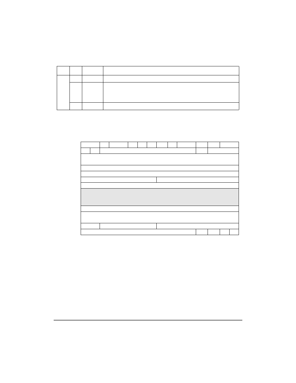
29.10.2.3 Transmit Connection Table (TCT)
Figure 29-30 shows the format of an TCT entry.
Table 29-21 describes general TCT Þelds.
0x18
0Р7
С
Reserved, should be cleared.
8
RXBM
Receive buffer interrupt mask
0 The receive buffer event of this channel is masked. (The RXB event is not sent to the
interrupt queue when receive buffers are closed.)
1 The receive buffer event of this channel is enabled.
9Р15
С
Reserved, should be cleared.
0
1
2
3
4
5
6
7
8
9
10
11
12
13
14
15
Offset + 0x00
Ñ
GBL
BO
Ñ
DTB BIB AVCF
Ñ
ATT
CPUU VCON
INTQ
Offset + 0x02
Ñ
INF
Ñ
ABRF
AAL
Offset + 0x04
Tx Data Buffer Pointer (TXDBPTR)
Offset + 0x06
Offset + 0x08
TBDCNT
Offset + 0x0A
TBD_OFFSET
Offset + 0x0C
Rate Remainder
PCR Fraction
Offset + 0x0E
PCR
Offset + 0x10
Protocol SpeciÞc
Offset + 0x12
Offset + 0x14
Offset + 0x16
APC Linked Channel (APCLC)
Offset + 0x18
ATM Cell Header (VPI,VCI,PTI,CLP)
Offset + 0x1a
Offset + 0x1C
Ñ
PMT
TBD_BASE
Offset + 0x1E
TBD_BASE
BNM
STPT
IMK
PM
Figure 29-30. Transmit Connection Table (TCT) Entry
Table 29-20. AAL0-Specific RCT Field Descriptions (Continued)
Offset
Bits
Name
Description