2 using interrupts in automatic data forwarding, Using interrupts in automatic data forwarding -35, Atm-to-tdm interworking -35 – Motorola MPC8260 User Manual
Page 815: Wn in figure 29-21
29-35
MPC8260 PowerQUICC II UserÕs Manual
MOTOROLA
Part IV. Communications Processor Module
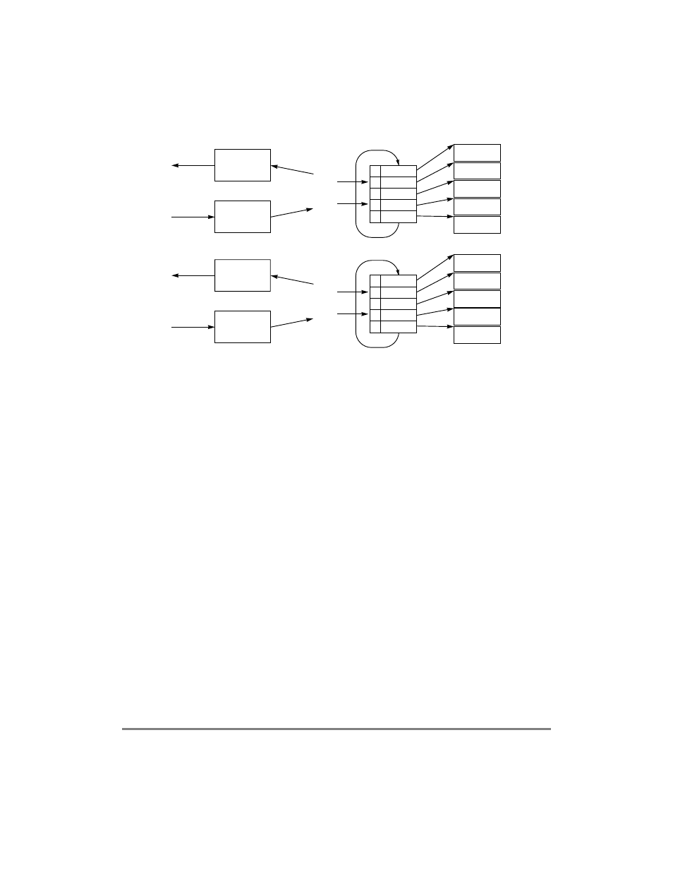
Figure 29-21. ATM-to-TDM Interworking
When going from TDM to ATM, the MCC receiver routes data from the TDM line to a
speciÞc BD table. The ATM controller transmitter is programmed to operate on the same
table. When the MCC Þlls a receive buffer, the ATM controller sends it. The two controllers
synchronize on the MCCÕs RxBD[E] and the ATM controllerÕs TxBD[R].
When going from ATM to TDM, the ATM receiver reassembles data received from a
particular channel to a speciÞc BD table. The MCC transmitter is programmed to operate
on the same table. When the ATM controller Þlls a receive buffer, the MCC controller sends
it. The controllers synchronize on the ATM controllerÕs RxBD[E] and the MCCÕs TxBD[R].
The MCC and ATM receivers must be programmed to operate in opposite E-bit polarity.
That is, both receivers receive data into buffers whose RxBD[E] = 0 and set RxBD[E] when
a buffer is full. For the ATM receiver, set RCT[INVE] of the AAL1- and AAL0-speciÞc
areas of the receive connection table; see Section 29.10.2.2, ÒReceive Connection Table
(RCT).Ó For the MCC receiver, set CHAMR[EP]; see Section 27.7.1, ÒChannel Mode
Register (CHAMR)ÑTransparent Mode.Ó
29.9.2 Using Interrupts in Automatic Data Forwarding
The core can program the MCC and ATM interrupt mechanism to trigger interrupts for
events such as a buffer closing or transfer errors. The interrupt mechanism can be used to
synchronize the start of the automatic bridging process. For example, to start the MCC
transmitter after a speciÞc buffer reaches the ATM receiver (the buffering is required to
MCC
Transmitter
TDM Interface
Buffer 1
Buffer 2
Buffer 3
Buffer 4
Buffer 5
ATM*
Receiver
UTOPIA Interface
BD Table
0
BD 1
1
BD 2
1
BD 3
0
BD 4
0
BD 5
MCC Tx ptr
ATM Rx ptr
ATM
Transmitter
UTOPIA Interface
Buffer 1
Buffer 2
Buffer 3
Buffer 4
Buffer 5
MCC*
Receiver
TDM Interface
BD Table
0
BD 1
1
BD 2
1
BD 3
0
BD 4
0
BD 5
ATM Tx ptr
MCC Rx ptr
* The MCC and ATM receivers should be programmed to operate in opposite polarity E (empty) bit.