3 timer mode registers (tmr1–tmr4), Timer mode registers (tmr1ðtmr4) -6, Tmriðtmr4 field descriptions -6 – Motorola MPC8260 User Manual
Page 520: 3 timer mode registers (tmr1ðtmr4)
17-6
MPC8260 PowerQUICC II UserÕs Manual
MOTOROLA
Part IV. Communications Processor Module
17.2.3 Timer Mode Registers (TMR1ÐTMR4)
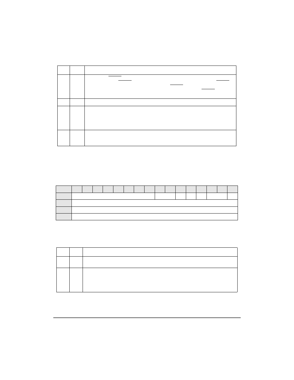
The four timer mode registers (TMR1ÐTMR4) are shown in Figure 17-5.
Erratic behavior may occur if TGCR1 and TGCR2 are not initialized before the TMRs.
Only TGCR[RST] can be modiÞed at any time.
Table 17-3 describes TMR1ÐTMR4 register Þelds.
4
GM2
Gate mode for TGATE2. This bit is valid only if the gate function is enabled in TMR3 or TMR4.
0 Restart gate mode. TGATE2 is used to enable/disable the count. The falling edge of TGATE2
enables and restarts the count and the rising edge of TGATE2 disables the count.
1 Normal gate mode. This mode is the same as 0, except the falling edge of TGATE2 does not
restart the count value in TCN.
5
Ñ
Reserved, should be cleared.
6
STP3
Stop timer.
0 Normal operation.
1 Reduce power consumption of the timer. This bit stops all clocks to the timer, however it is
possible to read the values while the clock is stopped. The clocks to the timer remain stopped
until the user clears this bit or a hardware reset occurs.
7
RST3
Reset timer.
0 Reset the corresponding timer (a software reset is identical to an external reset).
1 Enable the corresponding timer if STP = 0.
Bits
0
1
2
3
4
5
6
7
8
9
10
11
12
13
14
15
Field
PS
CE
OM
ORI
FRR
ICLK
GE
Reset
0000_0000_0000_0000
R/W
R/W
Addr
0x10D90 (TMR1); 0x10D92 (TMR2); 0x10DA0 (TMR3); 0x10DA2 (TMR4)
Figure 17-5. Timer Mode Registers (TMR1ÐTMR4)
Table 17-3. TMRIÐTMR4 Field Descriptions
Bits
Name
Description
0Ð7
PS
Prescaler value. The prescaler is programmed to divide the clock input by values from 1 to 256. The
value 00000000 divides the clock by 1 and 11111111 divides the clock by 256.
8Ð9
CE
Capture edge and enable interrupt.
00 Disable interrupt on capture event; capture function is disabled.
01 Capture on rising TINx edge only and enable interrupt on capture event.
10 Capture on falling TINx edge only and enable interrupt on capture event.
11 Capture on any TINx edge and enable interrupt on capture event.
Table 17-2. TGCR2 Field Descriptions (Continued)
Bit
Name
Description