2 risc timer command register (tm_cmd), Risc timer command register (tm_cmd) -20, Risc timer table parameter ram -20 – Motorola MPC8260 User Manual
Page 450
13-20
MPC8260 PowerQUICC II UserÕs Manual
MOTOROLA
Part IV. Communications Processor Module
The RISC timer table parameter RAM area begins at the RISC timer base address and is
used for the general timer parameters; see Table 13-11.
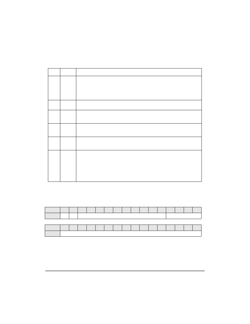
13.6.2 RISC Timer Command Register (TM_CMD)
Figure 13-10 shows the RISC timer command register (TM_CMD).
Table 13-11. RISC Timer Table Parameter RAM
Offset
1
1
Offset from timer base address (0x8AE0)
Name
Description
0x00
TM_BASE RISC timer table base address. The actual timers are a small block of memory in the dual-port
RAM. TM_BASE is the offset from the beginning of the dual-port RAM where that block resides.
Four bytes must be reserved at the TM_BASE for each timer used, (64 bytes if all 16 timers are
used). If fewer than 16 timers are used, timers should be allocated in ascending order to save
space. For example, only 8 bytes are required if two timers are needed and RISC timers 0 and 1
are enabled. TM_BASE should be word-aligned.
0x02
TM_PTR
RISC timer table pointer. This value is used exclusively by the CP to point to the next timer
accessed in the timer table. It should not be modiÞed by the user.
0x04
R_TMR
RISC timer mode register. This value is used exclusively by the CP to store the mode of the
timerÑone-shot (bit is 0) or restart (bit is 1). R_TMR should not be modiÞed by the user. The
SET
TIMER
command should be used instead.
0x06
R_TMV
RISC timer valid register. Used exclusively by the CP to determine if a timer is currently
enabled. If the corresponding timer is enabled, a bit is 1. R_TMV should not be modiÞed by the
user. The
SET
TIMER
command should be used instead.
0x08
TM_CMD RISC timer command register. Used as a parameter location when the
SET
TIMER
command is
issued. The user should write this location before issuing the
SET
TIMER
command. This register
is deÞned in Section 13.6.2, ÒRISC Timer Command Register (TM_CMD).Ó
0x0C
TM_CNT
RISC timer internal count. A tick counter that the CP updates after each tick. The update occurs
after the CP complete scanning the timer table.All 16 timers are scanned every tick interval
regardless of whether any of them is enabled.It is updated if the CPÕs internal timer is enabled,
regardless of whether any of the 16 timers are enabled and it can be used to track the number
of ticks the CP receives and responds to.TM_CNT is updated only after the last timer (timer 15)
has been serviced. If the CP is so busy with other tasks that it does not have time to service all
the timers during a tick interval, and timer 15 has not been serviced, then TM_CNT would not
be updated in that tick interval.
Bits
0
1
2
3
4
5
6
7
8
9
10
11
12
13
14
15
Field
V
R
Ñ
TN
Bits
16
17
18
19
20
21
22
23
24
25
26
27
28
29
30
31
Field
TIMER PERIOD (TP)
Figure 13-10. RISC Timer Command Register (TM_CMD)