5 programming model, 1 hdlc command set, Programming model -5 – Motorola MPC8260 User Manual
Page 907: Hdlc command set -5, Hdlc address recognition example -5, Transmit commands -5
MOTOROLA
Chapter 31. FCC HDLC Controller
31-5
Part IV. Communications Processor Module
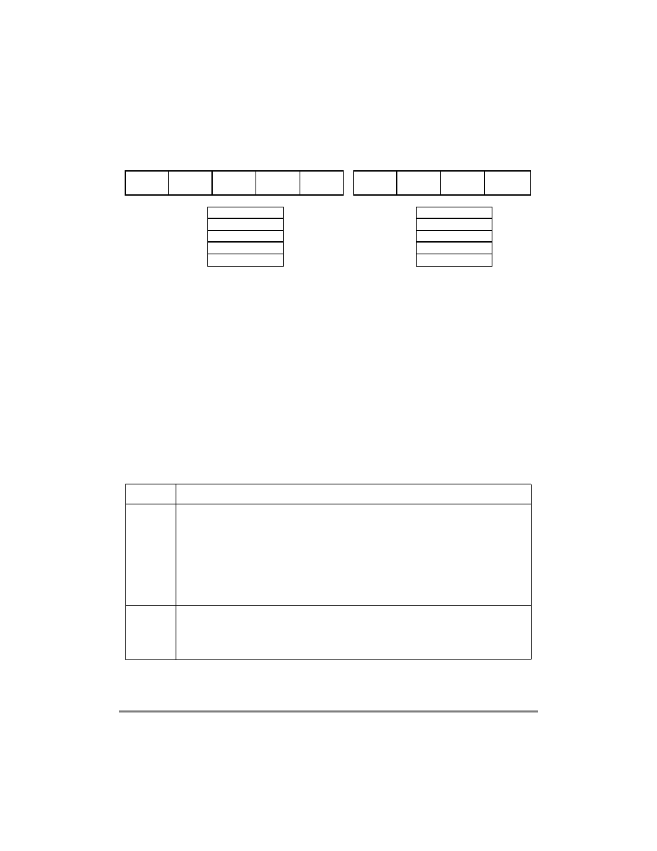
Figure 31-2 shows an example of using HMASK and HADDR[1Ð4].
Figure 31-2. HDLC Address Recognition Example
31.5 Programming Model
The core conÞgures each FCC to operate in the protocol speciÞed in GFMR[MODE]. The
HDLC controller uses the same data structure as other modes. This data structure supports
multibuffer operation and address comparisons.
31.5.1 HDLC Command Set
The transmit and receive commands are issued to the CPCR; see Section 13.4, ÒCommand
Set.Ó
Table 31-2 describes the transmit commands that apply to the HDLC controller.
Table 31-2. Transmit Commands
Command Description
STOP
TRANSMIT
After the hardware or software is reset and the channel is enabled in the FCC mode register, the
channel is in transmit enable mode and starts polling the Þrst BD in the table every 256 transmit clocks
(immediately if TODR[TOD] = 1).
STOP
TRANSMIT
command disables the transmission of frames on the
transmit channel. If this command is received by the HDLC controller during frame transmission,
transmission is aborted after a maximum of 64 additional bits are sent and the transmit FIFO buffer is
ßushed. The TBPTR is not advanced, no new BD is accessed, and no new frames are sent for this
channel. The transmitter sends an abort sequence consisting of 0x7F (if the command was given
during frame transmission) and begins sending ßags or idles, as indicated by the HDLC mode register.
Note that if FPSMR[MFF] = 1, one or more small frames can be ßushed from the transmit FIFO buffer.
The
GRACEFUL
STOP
TRANSMIT
command can be used to avoid this.
GRACEFUL
STOP
TRANSMIT
Used to stop transmission smoothly rather than abruptly, as performed by the regular
STOP
TRANSMIT
command. It stops transmission after the current frame Þnishes sending or immediately if no frame is
being sent. FCCE[GRA] is set once transmission has stopped. Then the HDLC transmit parameters
(including BDs) can be modiÞed. The TBPTR points to the next TxBD in the table. Transmission begins
once the R bit of the next BD is set and the
RESTART
TRANSMIT
command is issued.
HMASK
8-Bit Address Recognition
Address
0x68
Control
0x44
Flag
0x7E
Address
0xAA
etc.
16-Bit Address Recognition
0xFFFF
0xAA68
0xFFFF
0xAA68
0xAA68
HMASK
Address
0x55
Control
0x44
Flag
0x7E
etc.
0x00FF
0xXX55
0xXX55
0xXX55
0xXX55
HADDR1
HADDR2
HADDR3
HADDR4
HADDR1
HADDR2
HADDR3
HADDR4
Recognizes one 16-bit address (HADDR1) and
the 16-bit broadcast address (HADDR2)
Recognizes one 8-bit address (HADDR1)