5 controlling scc timing with rts, cts, and cd, 1 synchronous protocols, Controlling scc timing with rts, cts, and cd -18 – Motorola MPC8260 User Manual
Page 574
19-18
MPC8260 PowerQUICC II UserÕs Manual
MOTOROLA
Part IV. Communications Processor Module
19.3.5 Controlling SCC Timing with RTS, CTS, and CD
When GSMR_L[DIAG] is programmed to normal operation, CD and CTS are controlled
by the SCC. In the following subsections, it is assumed that GSMR_L[TCI] is zero,
implying normal transmit clock operation.
19.3.5.1 Synchronous Protocols
RTS is asserted when the SCC data is loaded into the Tx FIFO and a falling Tx clock occurs.
At this point, the SCC starts sending data once appropriate conditions occur on CTS. In all
cases, the Þrst data bit is the start of the opening ßag, sync pattern, or preamble.
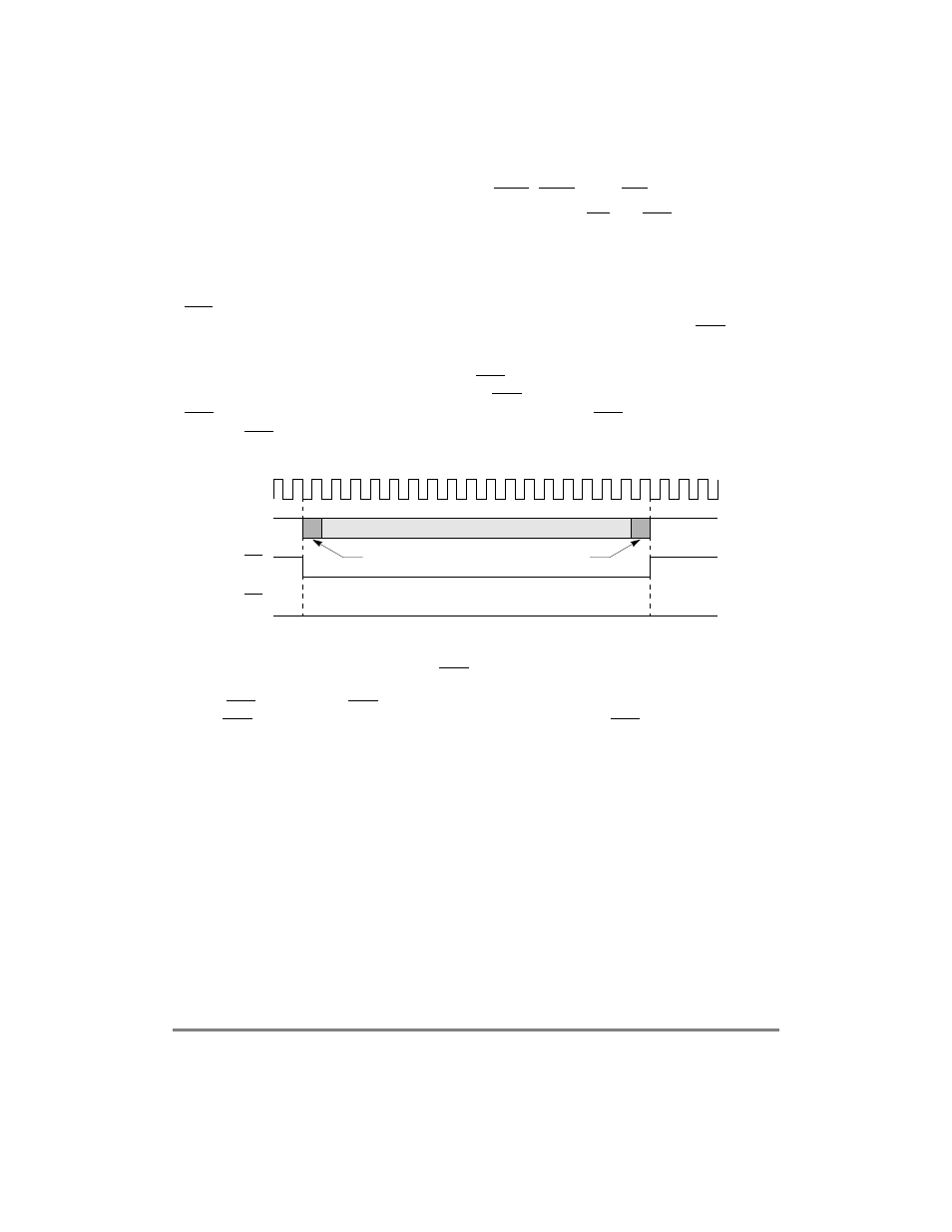
Figure 19-9 shows that the delay between RTS and data is 0 bit times, regardless of
GSMR_H[CTSS]. This operation assumes that CTS is already asserted to the SCC or that
CTS is reprogrammed to be a parallel I/O line, in which case CTS to the SCC is always
asserted. RTS is negated one clock after the last bit in the frame.
Figure 19-9. Output Delay from RTS Asserted for Synchronous Protocols
When RTS is asserted, if CTS is not already asserted, delays to the Þrst data bit depend on
when CTS is asserted. Figure 19-10 shows that the delay between CTS and the data can be
approximately 0.5 to 1 bit times or 0 bit times, depending on GSMR_H[CTSS].
1. A frame includes opening and closing flags and syncs, if present in the protocol.
TCLK
TXD
Last Bit of Frame Data
First Bit of Frame Data
NOTE
:
(Output)
RTS
(Output)
CTS
(Input)