Motorola MPC8260 User Manual
Page 213
MOTOROLA
Chapter 6. External Signals
6-11
Part III. The Hardware Interface
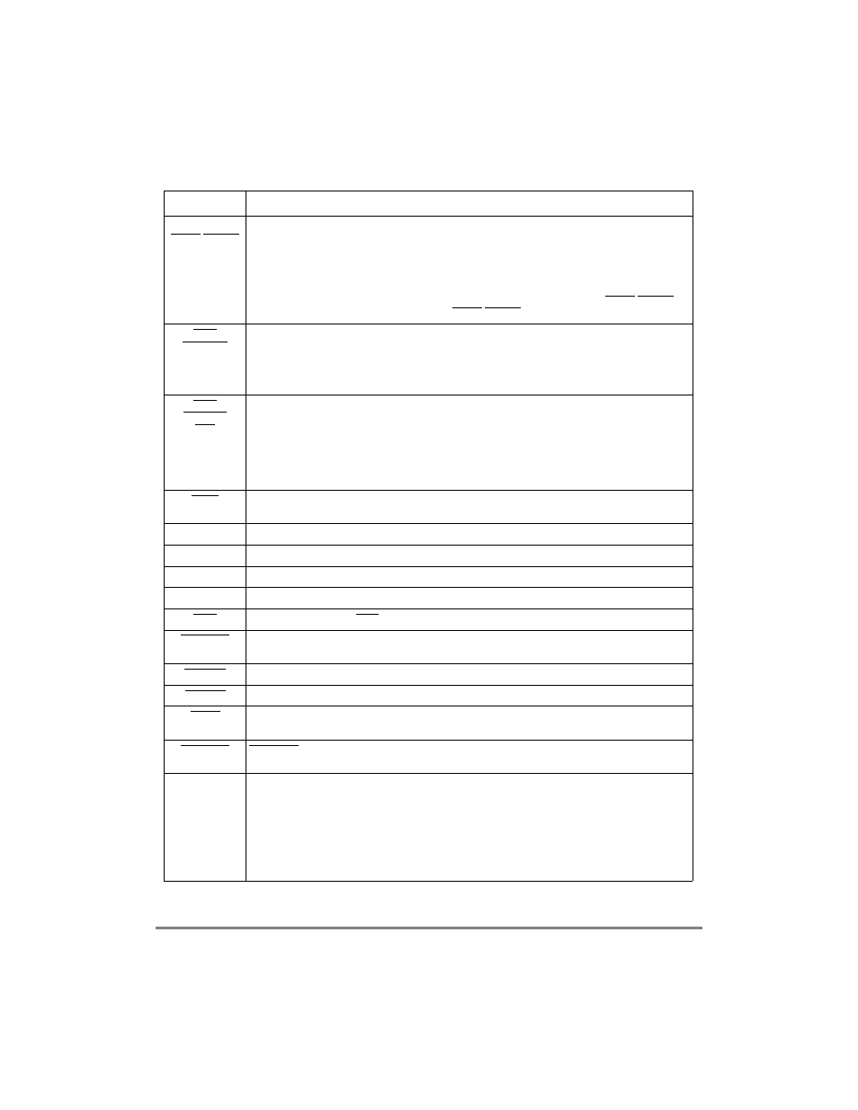
LCL_DP[0Ð3]
PCI_C/BE[0Ð3]
Local bus data parityÑLocal bus data parity input/output pins. In local bus write operations the
MPC8260 drives these pins. In local bus read operations the accessed device drives these pins.
LCL_DP[0] is driven with a value that gives odd parity with LCL_D[0Ð7]. LCL_DP[1] is driven with a
value that gives odd parity with LCL_D[8Ð15]. LCL_DP[2] is driven with a value that gives odd parity
with LCL_D[16Ð23]. LCL_DP[3] is driven with a value that gives odd parity with LCL_D[24Ð31].
PCI command/byte enableÑPCI command/byte enable input/output pins. The MPC8260 drives
these pins when it is the initiator of a PCI transfer. During an address phase the PCI_C/BE[0Ð3]
deÞnes the command, during the data phase PCI_C/BE[0Ð3] deÞnes the byte enables.
IRQ0
NMI_OUT
Interrupt request 0ÑThis input is one of the eight external lines that can request (by means of the
internal interrupt controller) a service routine from the core.
Non-maskable interrupt outputÑThis is an output driven from MPC8260Õs internal interrupt
controller. Assertion of this output indicates that an unmasked interrupt is pending in MPC8260Õs
internal interrupt controller.
IRQ7
INT_OUT
APE
Interrupt request 7ÑThis input is one of the eight external lines that can request (by means of the
internal interrupt controller) a service routine from the core.
Interrupt outputÑThis is an output driven from MPC8260Õs internal interrupt controller. Assertion of
this output indicates that an unmasked interrupt is pending in MPC8260Õs internal interrupt
controller.
Address parity errorÑThis output pin will be asserted when the MPC8260 detects wrong parity
driven on its address parity pins by an external master.
TRST
Test reset (JTAG)Ñ Input only. This is the reset input to MPC8260Õs JTAG/COP controller. See
Section 12.1, ÒOverview,Ó and Section 12.6, ÒNonscan Chain Operation.Ó
TCK
Test clock (JTAG)ÑInput only. Provides the clock input for MPC8260Õs JTAG/COP controller.
TMS
Test mode select (JTAG)ÑInput only. Controls the state of MPC8260Õs JTAG/COP controller.
TDI
Test data in (JTAG)ÑInput only. Data input to MPC8260Õs JTAG/COP controller.
TDO
Test data out (JTAG)ÑOutput only. Data output from MPC8260Õs JTAG/COP controller.
TRIS
Three-stateÑAsserting TRIS forces all other MPC8260Õs pins to high impedance state.
PORESET
Power-on resetÑWhen asserted, this input line causes the MPC8260 to enter power-on reset
state.
HRESET
Hard resetÑThis open drain line, when asserted causes the MPC8260 to enter hard reset state.
SRESET
Soft resetÑThis open drain line, when asserted causes the MPC8260 to enter the soft reset state.
QREQ
Quiescent requestÑ Output only. Indicates that MPC8260Õs internal core is about to enter its low
power mode. In the MPC8260 this pin will be typically used for debug purposes.
RSTCONF
RSTCONF -ÑInput used during reset conÞguration sequence of the chip. Find detailed explanation
of its function in Section 5.1.2, ÒPower-On Reset Flow,Ó and Section 5.4, ÒReset ConÞguration.Ó
MODCK1
AP[1]
TC[0]
BNKSEL[0]
MODCK1ÑClock mode input. DeÞnes the operating mode of internal clock circuits.
Address parity 1Ñ(Input/output)The 60x master that drives the address bus, drives also the
address parity signals. The value driven on address parity 1 pin should give odd parity (odd number
of 1s) on the group of signals that includes address parity 1 and A[8Ð15].
Transfer Code 0ÑThe transfer code output pins supply information that can be useful for debug
purposes for each of the MPC8260Õs initiated bus transactions.
Bank Select 0ÑThe bank select outputs are used for selecting SDRAM bank when the MPC8260 is
in 60x compatible bus mode.
Table 6-1. External Signals (Continued)
Signal Description