2 apc priority table, 3 apc scheduling tables, Apc priority table -63 – Motorola MPC8260 User Manual
Page 843: Apc scheduling tables -63, The apc scheduling table structure -63, Control slot -63, Apc priority table entry -63
29-63
MPC8260 PowerQUICC II UserÕs Manual
MOTOROLA
Part IV. Communications Processor Module
29.10.4.2 APC Priority Table
Each PHYÕs APC priority table holds pointers to the APC scheduling table of each priority
level. It resides in the dual-port RAM. The priority table can hold up to eight priority levels.
Table 29-30 shows the structure of a priority table entry.
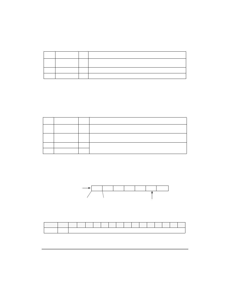
29.10.4.3 APC Scheduling Tables
The APC uses APC scheduling tables (one table for each priority level) to schedule channel
transmission. A scheduling table is divided into time slots, as shown in Figure 29-39. Each
slot is a half-word entry. Note that the APC scheduling tables should be cleared before the
APC unit is enabled.
Figure 29-39. The APC Scheduling Table Structure
Slot N+1 is used as a control slot, as shown in Figure 29-40.
0x0A
LINE_RATE_AB
R
Hword ABR only. The PHY line rate in cells/sec, represented in TM 4.0 ßoating-point
format. User-deÞned.
0xC
REAL_TSTP
Word
Real-time stamp pointer used internally by the APC. Initialize to 0.
0x10
APC_STATE
Word
Used internally by the APC. Initialize to 0.
1
Offset values are to APCP_BASE+PHY#
´ 32. However, in slave mode, the offset is from APCP_BASE regard-
less of the PHY address.
Table 29-30. APC Priority Table Entry
Offset Name
Width
Description
0x00
APC_LEVi_BASE Hword
APC level i base address. Pointer to the first slot in the APC scheduling table for
level i. Should be half-word aligned. User-deÞned.
0x02
APC_LEVi_END
Hword
APC level i end address. Pointer to the last slot in the APC scheduling table for
level i. Should be half-word aligned. User-deÞned.
0x04
APC_LEVi_RPTR Hword
APC level i real-time/service pointers. APC table pointers used internally by the
APC. Initialize both pointers to APC_LEVi_BASE.
0x06
APC_LEVi_SPTR Hword
Bits
0
1
2
3
4
5
6
7
8
9
10
11
12
13
14
15
Field
TCTE
000_0000_0000_0000
Figure 29-40. Control Slot
Table 29-29. APC Parameter Table (Continued)
Offset
1
Name
Width
Description
APC_LEVi_BASE
APC_LEVi_END
Half Word Entry
slot 0
slot 1
slot N
Control
Slot