2 rm cell structure, Rm cell structure -25, Abr receive flow -25 – Motorola MPC8260 User Manual
Page 805
29-25
MPC8260 PowerQUICC II UserÕs Manual
MOTOROLA
Part IV. Communications Processor Module
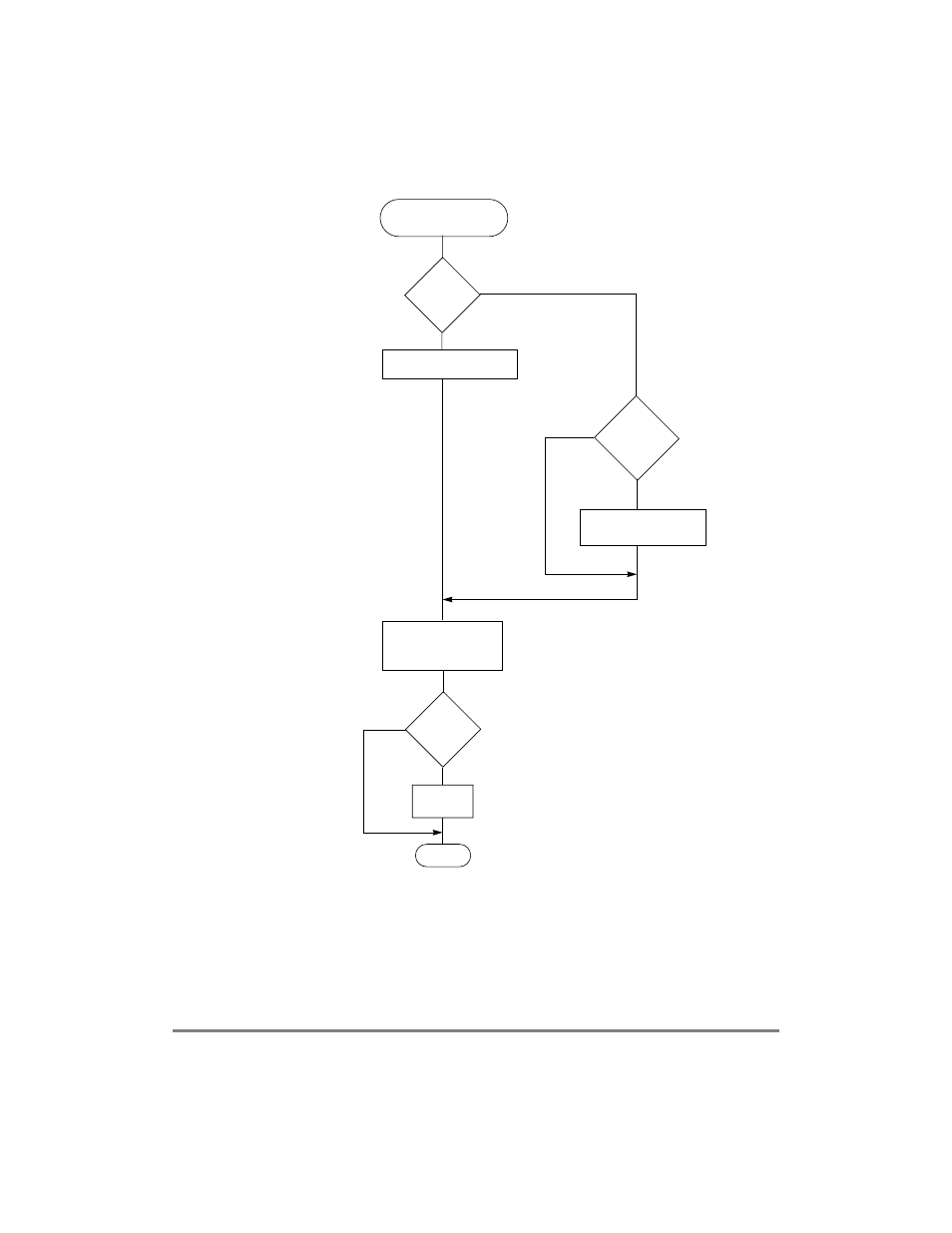
Figure 29-14. ABR Receive Flow
29.5.2 RM Cell Structure
Table 29-7 describes the structure of the RM cell supported by the MPC8260. For more
information, see the ABR ßow-control trafÞc management speciÞcation (TM 4.0) on the
ATM Forum website at http://www.atmforum.com.
B-RM Cells Rx
CI = 1
ACR = ACR-ACR
´RDF
NI = 0
ACR = ACR+RIF
´PCR
ACR = min(ACR,PCR)
ACR = min(ACR,ER)
ACR = max(ACR,MCR)
BN = 0
Unack = 0
EXIT
The source generate this RM
Unack = Number of F-RM in absence of B-RM = 0
Source End-Sys 5
Source End-Sys 1, 6
Source End-Sys 5, 6
Yes
No
Yes
No
No
Yes
See also other documents in the category Motorola Hardware:
- SB5101U DOCSIS 2.0 Cable Modem (16 pages)
- PTP 500 (20 pages)
- Netopia 3347-02-ENT (3 pages)
- SBV5220 (64 pages)
- AP-51XX (698 pages)
- SURFboard SVG2501 Series (34 pages)
- MESH Wireless Router MWR6300 (2 pages)
- MVME712AM (74 pages)
- SURFBOARD SBG1000 (16 pages)
- RSGu3502 (5 pages)
- SURFboard SBG941U (78 pages)
- Netopia 2240N-VGx (5 pages)
- SURFboard SVG2501 (8 pages)
- WR850G (93 pages)
- WR850GP (95 pages)
- USBW 200 (12 pages)
- ONCE SC140 (28 pages)
- Netopia 3300 (368 pages)
- WNS25 (2 pages)
- Netopia 7000 (254 pages)
- Viadux 2000 Subscriber Bridge RC2010 (1 page)
- MVME5100 Series (5 pages)
- ColdFire MCF5282 (766 pages)
- MC9S12C-Family (136 pages)
- CG4500 (36 pages)
- SBG900 (130 pages)
- SURFBOARD SB5100 (2 pages)
- SURFboard SB6180 (20 pages)
- SURFBOARD SBG900 (16 pages)
- SURFboard SVG1501U (83 pages)
- SB5100 (74 pages)
- T3 (2 pages)
- H375 (5 pages)
- NETOPIA 2247/57-62 (22 pages)
- SBV5120 (57 pages)
- SBV5120 (56 pages)
- RG2200 (88 pages)
- CME-12B/BC (18 pages)
- SURFboard 574823-001-a (2 pages)
- SURFboard Cable Modem (66 pages)
- CME-12D60 (19 pages)
- DIGITAL VOICE MODEM SBV5122 (24 pages)
- SB4000 (2 pages)
- Canopy FSK and OFDM radios PTP 200 (OFDM (56 pages)