1 cmx utopia address register (cmxuar), Cmx utopia address register (cmxuar) -7, Cmxuar field descriptions -7 – Motorola MPC8260 User Manual
Page 497
MOTOROLA
Chapter 15. CPM Multiplexing
15-7
Part IV. Communications Processor Module
15.4.1 CMX UTOPIA Address Register (CMXUAR)
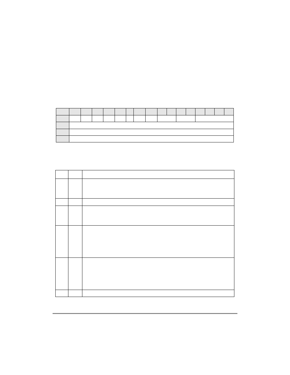
The CMX UTOPIA address register (CMXUAR), shown in Figure 15-4, deÞnes the
connection of FCC1 and FCC2 UTOPIA multiple-PHY addresses to the twenty UTOPIA
address pins of the MPC8260; it also deÞnes the connection of a BRG to the FCCs when
an internal rate feature is used. This enables the user to implement a multiple-PHY
UTOPIA master or slave on both FCC1 and FCC2 using only twenty pins. The user chooses
how many PHYs to use with each interface and how many address lines are needed for each
FCC.
Table 15-2 describes CMXUAR Þelds.
Bits
0
1
2
3
4
5
6
7
8
9
10
11
12
13
14
15
Field
SAD0 SAD1 SAD2 SAD3 SAD4
Ñ
MAD4 MAD3
F1IRB
F2IRB
Ñ
Reset
0000_0000_0000_0000
R/W
R/W
Addr
Figure 15-4. CMX UTOPIA Address Register (CMXUAR)
Table 15-2. CMXUAR Field Descriptions
Bits
Name
Description
0Ð4
SADx
Slave address input pin x connection. Note that the address indexes are relative to FCC1; see
Figure 15-7.
0 This address input pin is used by FCC2 in slave mode.
1 This address input pin is used by FCC1 in slave mode.
5
Ñ
Reserved, should be cleared.
6Ð7
MADx
Master address output pin x connection. Note that the address indexes are relative to FCC1; see
Figure 15-7.
0 This address output pin is used by FCC2 in master mode.
1 This address output pin is used by FCC1 in master mode.
8Ð9
F1IRB
FCC1 internal rate BRG selection. Selects the BRG to be connected to FCC 1 for internal rate
operation. Used by the ATM controller; see Section 29.2.1.4, ÒTransmit External Rate and Internal
Rate Modes.Ó
00 FCC1 internal rate clock is BRG5.
01 FCC1 internal rate clock is BRG6.
10 FCC1 internal rate clock is BRG7.
11 FCC1 internal rate clock is BRG8.
10Ð11
F12IRB FCC2 internal rate BRG selection. Selects the BRG to be connected to FCC 2 for internal rate
operation. Used by the ATM controller; see Section 29.2.1.4, ÒTransmit External Rate and Internal
Rate Modes.Ó
00 FCC2 internal rate clock is BRG5.
01 FCC2 internal rate clock is BRG6.
10 FCC2 internal rate clock is BRG7.
11 FCC2 internal rate clock is BRG8.
12Р15
С
Reserved, should be cleared.