2 receive connection table (rct), Receive connection table (rct) -43 – Motorola MPC8260 User Manual
Page 823
29-43
MPC8260 PowerQUICC II UserÕs Manual
MOTOROLA
Part IV. Communications Processor Module
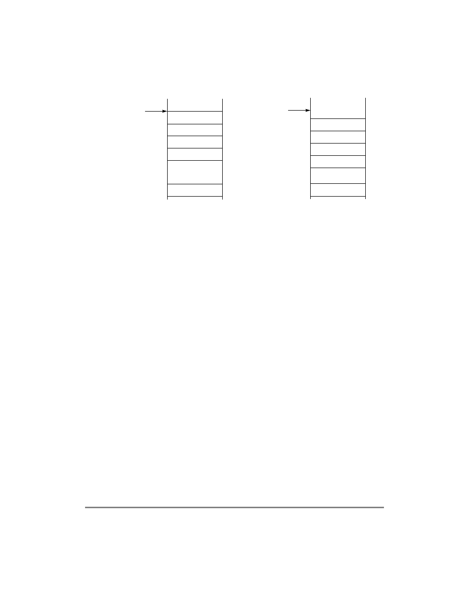
Figure 29-24. Example of a 1024-Entry Receive Connection Table
The general formula for determining the real starting address for all internal and external
connection table entries is as follows:
connection table base address + (channel code
´ 32)
Thus, the real starting address of the RCT entry associated with channel code 3 is as
follows:
INT_RCT_BASE+ (3
´ 32) = INT_RCT_BASE + 96
Even though it produces a gap in the connection table, the Þrst external channelÕs real
starting address of the RCT entry (channel code 256) is as follows:
EXT_RCT_BASE+ (256
´ 32) = EXT_RCT_BASE + 8192
See Section 29.10.1, ÒParameter RAM,Ó to Þnd all the connection table base address
parameters. (The transmit connections table base address parameters are INT_TCT_BASE,
EXT_TCT_BASE, INT_TCTE_BASE, and EXT_TCTE_BASE.)
29.10.2.2 Receive Connection Table (RCT)
Figure 29-25 shows the format of an RCT entry.
Dual-Port RAM
INT_RCT_BASE
Reserved
RCT2
RCT3
RCT63
External Memory
EXT_RCT_BASE
RCT256
RCT257
RCT258
RCT259
RCT1217
Raw Cell (AAL0)