Simple system configuration -7 – Motorola MPC8260 User Manual
Page 283
MOTOROLA
Chapter 10. Memory Controller
10-7
Part III. The Hardware Interface
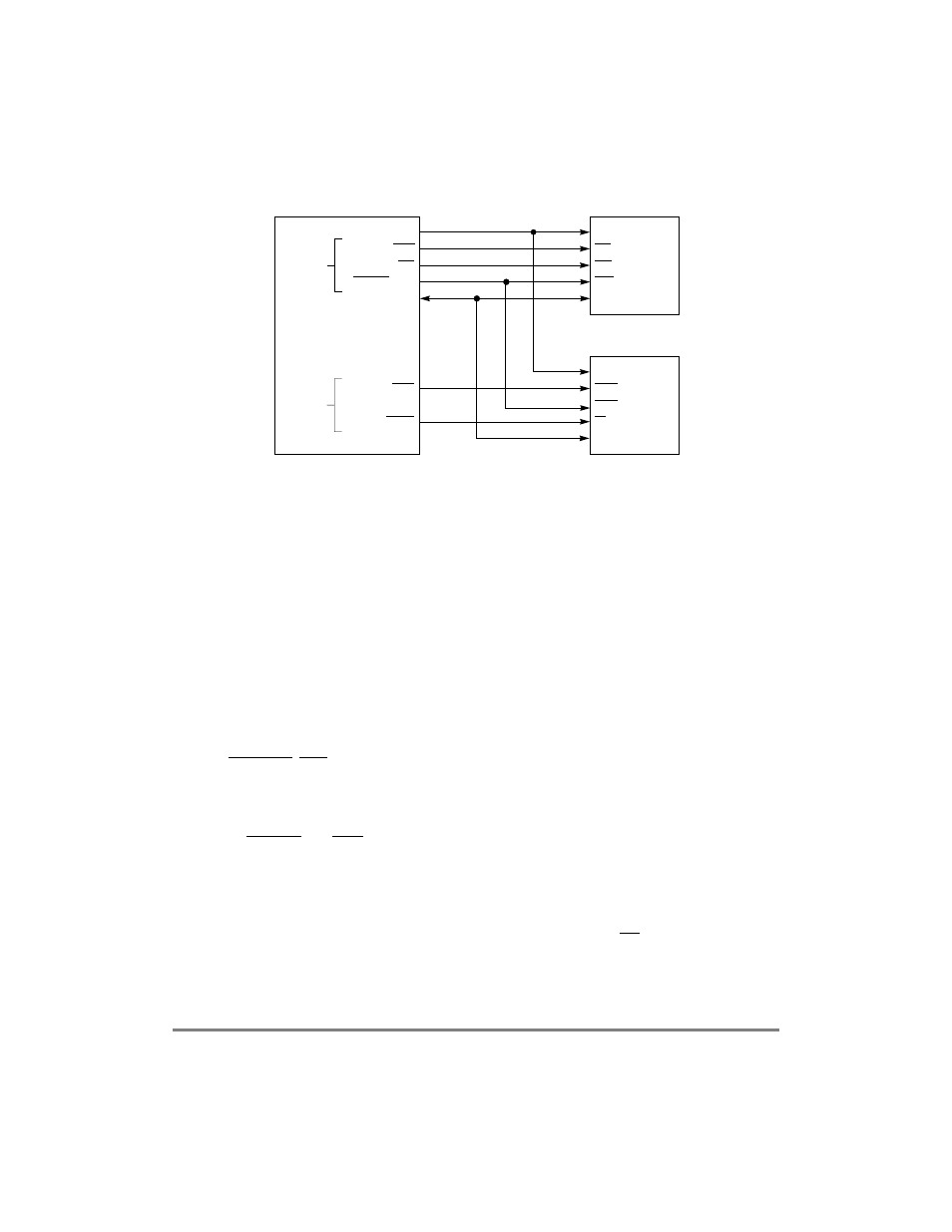
Figure 10-3. Simple System Configuration
Implementation differences between the supported machines are described in the
following:
¥
The SDRAM machine provides a glueless interface to JEDEC-compliant SDRAM
devices, and using SDRAM pipelining, page mode, and bank interleaving delivers
very high performance. To allow Þne tuning of system performance, the SDRAM
machine provides two types of page modes selectable per memory bank:
Ñ Page mode for consecutive back-to-back accesses (normal operation)
Ñ Page mode for intermittent accesses
SDRAM machines are available on the 60x and local buses; each memory bank can
be assigned to any SDRAM machine.
¥
The GPCM provides a glueless interface to EPROM, SRAM, ßash EPROM
(FEPROM), and other peripherals. The GPCM is available on both buses on
CS[0Ð11]. CS0 also functions as the global (boot) chip-select for accessing the boot
EPROM or FLASH device. The chip-select allows 0 to 30 wait states.
¥
The UPMs provide a ßexible interface to many types of memory devices. Each UPM
can control the address multiplexing for accessing DRAM devices and the timings
of BS[0Ð7] and GPL. Each UPM can be assigned either to the 60x or to the local
bus. Each memory bank can be assigned to any UPM.
Each UPM is a programmable RAM-based machine. The UPM toggles the memory
controller external signals as programmed in RAM when an internal or external
master initiates any external read or write access. The UPM also controls address
multiplexing, address increment, and transfer acknowledge (TA) assertion for each
memory access. The UPM speciÞes a set of signal patterns for a user-speciÞed
number of clock cycles. The UPM RAM pattern run by the memory controller is
Address
CE
OE
WE
Data
EPROM
RAS
CAS[0Ð7]
W
Data
DRAM
CS1
GPLx
Data
BS/WE[0Ð7]
GPL1/OE
CS0
Address
Address
UPMA
GPCM
MPC8260