8 hdlc mode register (psmr), Hdlc mode register (psmr) -7, Psmr hdlc field descriptions -7 – Motorola MPC8260 User Manual
Page 615: 8/21-7 (hdlc)
MOTOROLA
Chapter 21. SCC HDLC Mode
21-7
Part IV. Communications Processor Module
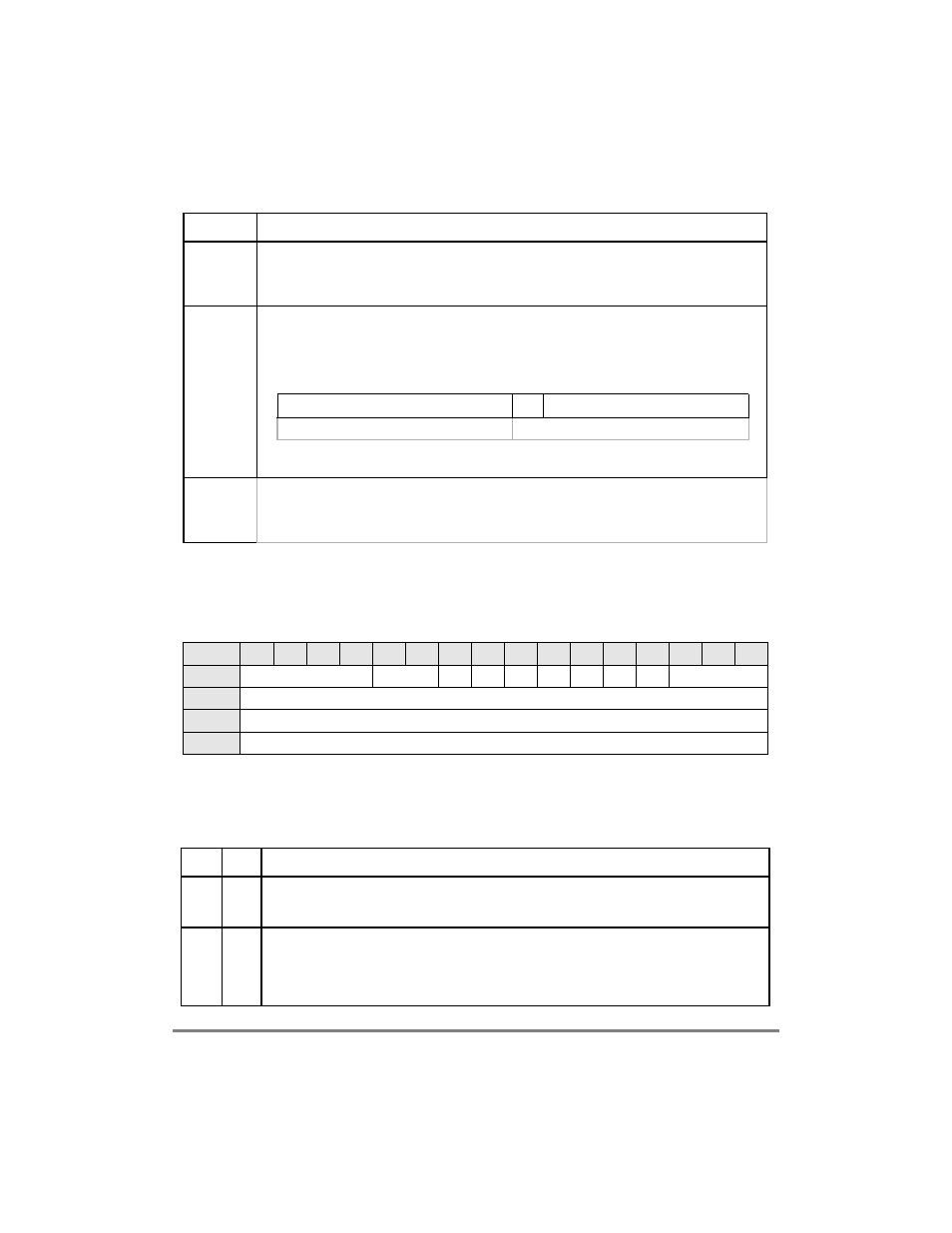
21.8 HDLC Mode Register (PSMR)
The protocol-speciÞc mode register (PSMR), shown in Figure 21-3, functions as the HDLC
mode register.
Table 21-6 describes PSMR HDLC Þelds.
Abort
Sequence
Occurs when seven or more consecutive ones are received. When this occurs while receiving a frame,
the channel closes the buffer, sets RxBD[AB] and generates a maskable RXF interrupt. The channel
also increments the abort sequence counter ABTSC. The CRC and nonoctet error status conditions
are not checked on aborted frames. The receiver then enters hunt mode.
Nonoctet
Aligned
Frame
The channel writes the received data to the buffer, closes the buffer, sets RxBD[NO], and generates a
maskable RXF interrupt. CRC error status should be disregarded on nonoctet frames. After a nonoctet
aligned frame is received, the receiver enters hunt mode. An immediate back-to-back frame is still
received. The nonoctet data may be derived from the last word in the buffer as follows:
Note that if buffer swapping is used (RFCR[BO] = 0b0x), the Þgure above refers to the last byte, rather
than the last word, of the buffer. The lsb of each octet is sent Þrst while the msb of the CRC is sent Þrst.
CRC
The channel writes the received CRC to the buffer, closes the buffer, sets RxBD[CR], generates a
maskable RXF interrupt, and increments the CRC error counter CRCEC. After receiving a frame with
a CRC error, the receiver enters hunt mode. An immediate back-to-back frame is still received. CRC
checking cannot be disabled, but the CRC error can be ignored if checking is not required.
Bit
0
1
2
3
4
5
6
7
8
9
10
11
12
13
14
15
Field
NOF
CRC
RTE
Ñ
FSE
DRT BUS BRM MFF
Ñ
Reset
0
R/W
R/W
Address
0x11A08 (PSMR1); 0x11A28 (PSMR2); 0x11A48 (PSMR3); 0x11A68 (PSMR4)
Figure 21-3. HDLC Mode Register (PSMR)
Table 21-6. PSMR HDLC Field Descriptions
Bits
Name
Description
0-3
NOF
Number of ßags. Minimum number of ßags between or before frames. If NOF = 0b0000, no ßags are
inserted between frames and the closing ßag of one frame is followed by the opening ßag of the next
frame in the case of back-to-back frames. NOF can be modiÞed on-the-Яy.
4Р5
CRC
CRC selection.
00 16-bit CCITT-CRC (HDLC). X16 + X12 + X5 + 1.
x1 Reserved.
10 32-bit CCITT-CRC (Ethernet and HDLC). X32 + X26 + X23 + X22 + X16 + X12 + X11 + X10 + X8
+ X7 + X5 + X4 + X2 + X1 +1.
Table 21-5. Receive Errors (Continued)
Error
Description
msb
lsb
1
0
0
Valid Data
Nonvalid Data