3 hreset flow, 4 sreset flow, Hreset – Motorola MPC8260 User Manual
Page 187: Flow, Sreset, Figure 5-3 sho ws the power-on reset ßow
MOTOROLA
Chapter 5. Reset
5-3
Part II. ConÞguration and Reset
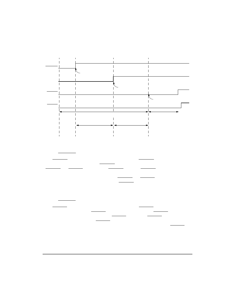
Figure 5-3 shows the power-on reset ßow.
5.1.3 HRESET Flow
The HRESET ßow may be initiated externally by asserting HRESET or internally when the
chip detects a reason to assert HRESET. In both cases the chip continues asserting
HRESET and SRESET throughout the HRESET ßow. The HRESET ßow begins with the
hard reset conÞguration sequence, which conÞgures the chip as explained in Section 5.4,
ÒReset ConÞguration.Ó After the chip asserts HRESET and SRESET for 1,024 input clock
cycles, it releases both signals and exits the HRESET ßow. An external pull-up resistor
should negate the signals. After negation is detected, a 16-cycle period is taken before
testing the presence of an external (hard/soft) reset.
5.1.4 SRESET Flow
The SRESET ßow may be initiated externally by asserting SRESET or internally when the
chip detects a cause to assert SRESET. In both cases the chip asserts SRESET for 512 input
clock cycles, after which the chip releases SRESET and exits the SRESET ßow. An external
pull-up resistor should negate SRESET; after negation is detected, a 16-cycle period is
taken before testing the presence of an external (hard/soft) reset. While SRESET is
asserted, internal hardware is reset but hard reset conÞguration does not change.
PORESET
PORESET
Internal
HRESET
Input
Output
SRESET
Output
External
pin is
asserted
for min 16
RSTCONF is sampled for
master determination
MODCK[1Ð3] are
sampled. MODCK_HI
bits are ready for PLL
PLL is locked (no
external indication)
HRESET /SRESET are
extended for 512/515
CLKIN (respectively), from
PLL lock time.
PLL locking period
PORESET to internal logic
is extended for 1024 CLKIN.
In reset conÞguration mode:
reset conÞguration
sequence occurs in this
period.
Interval depends on
PLL locking time.